RS-1_instruction manual.pdf - 第672页
Pa r t 2 D et ai l ed Des c r i pt i o n of Ea c h F unc t i o n Chapte r 6 G e neral - Purpose Vision Co mpone nt 6- 41 3. C om ponen t exam p le 2 Com p onent ap pear ance an d el em ent g r oup p os iti ons <Im age…
Part 2 Detailed Description of Each Function Chapter 6 General-Purpose Vision Component
6-40
Outline recognition component group (Element group/Element format) 6.5.3
♦ An example for entering data on an outline recognition component is shown below.
1. "Element Data" screen
• Select “Outline component” in the “Component Type” field.
• Select check box “Element group/Element format” in the “Define data format” column.
• Click the <Add> button on the “Element Group List.”
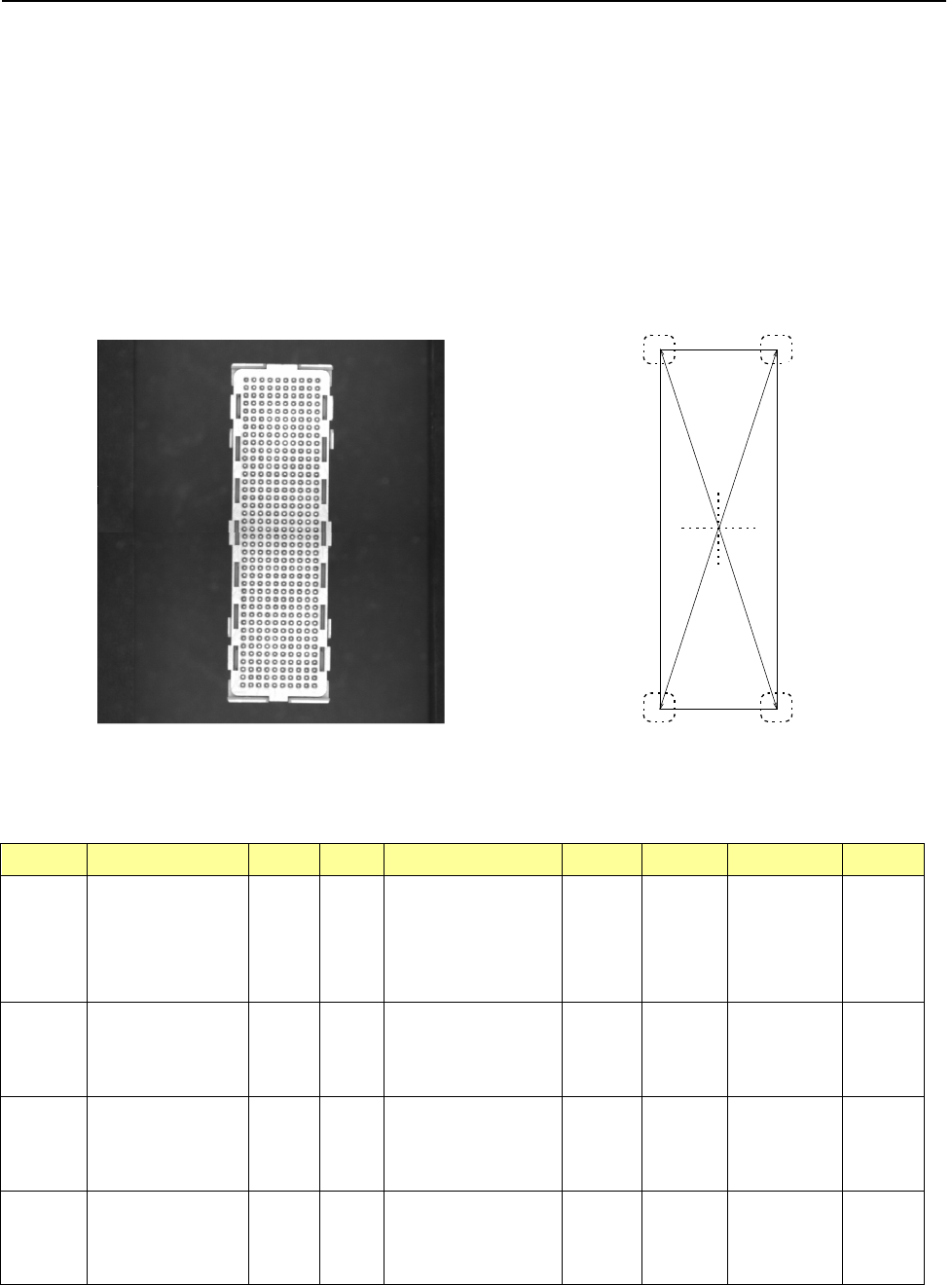
2. Component example 1
• Component appearance and element group positions
<Image of a component displayed on the
component monitor: Bottom view>
<Top view>
Summary of the input data
Element
Group Name
First element position (Layout)
Missing
Elements
Element
Element
Offset
Element
dimensions
(Corner) Remarks
ELG0001 X: -8.25
Y: -27.6
Z: 0
θ: 0
Tolerance:
all values are set to “0.”
Point Type: Corner
Reference pos.: Bottom left
Polarity: Bright
Offset: all
values are
set to “0.”
Tolerance:
all values are
set to “0.”
Radius: 0.5 Light data:
standard
settings of the
reflectance
light
Vertical
two-Split
recognition
ELG0002
X: 8.25
Y: -27.6
Z: 0
θ: 90
Tolerance:
all values are set to “0.”
Point
Type: Corner
Reference pos.: Bottom left
Polarity: Bright
Offset: all
values are
set to “0.”
Tolerance:
all values are
set to “0.”
Radius: 0.5
ELG0003 X: 8.25
Y: -27.6
Z: 0
θ: 90
Tolerance:
all values are set to “0.”
Point Type: Corner
Reference pos.: Bottom left
Polarity: Bright
Offset: all
values are
set to “0.”
Tolerance:
all values are
set to “0.”
Radius: 0.5
ELG0004
X: -8.25
Y: -27.6
Z: 0
θ: 0
Tolerance:
all values are set to “0.”
Point
Type: Corner
Reference pos.: Bottom left
Polarity: Bright
Offset: all
values are
set to “0.”
Tolerance:
all values are
set to “0.”
Radius: 0.5
第 1 エレメントグループ
第 2 エレメントグループ
第
3
エレメントグループ
第 4 エレメントグループ
Fourth element group
Second element group
First element group
Third element group
Part 2 Detailed Description of Each Function Chapter 6 General-Purpose Vision Component
6-41
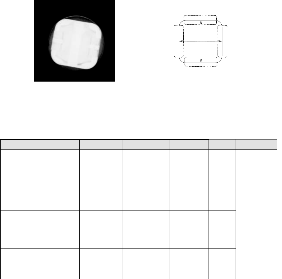
3. Component example 2
Component appearance and element group positions
<Image of a component displayed on the
component monitor: Bottom view>
<Top view>
Summary of the input data
Element
Group Name
First element position (Layout)
Missing
Elements
Element Element Offset
Element
dimensions
Inspection
ELG0001 X: 0
Y: -6
Z: 0
θ: 0
Tolerance: all values are
set to “0.”
Point Type: Side
Reference pos.: Bottom
Center
Polarity: Bright
Offset: all values
are set to “0.”
Tolerance: all
values are set to “0.”
Light data:
Transmittance light
ELG0001 X: 6
Y: 0
Z: 0
θ: 90
Tolerance: all values are
set to “0.”
Point Type: Side
Reference pos.: Bottom
Center
Polarity: Bright
Offset: all values
are set to “0.”
Tolerance: all
values are set to “0.”
ELG0001 X: 0
Y: 6
Z: 0
θ: 180
Tolerance: all values are
set to “0.”
Point Type: Side
Reference pos.: Bottom
Center
Polarity: Bright
Offset: all values
are set to “0.”
Tolerance: all
values are set to “0.”
ELG0001
X: -6
Y: 0
Z: 0
θ: 270
Tolerance: all values are
set to “0.”
Point
Type: Side
Reference pos.: Bottom
Center
Polarity: Bright
Offset: all values
are set to “0.”
Tolerance: all
values are set to “0.”
Fourth element group
Second element group
Third element group
First element group
Part 2 Detailed Description of Each Function Chapter 6 General-Purpose Vision Component
6-42
Limitations of a general-purpose vision component 6.6
1. Quantity
- Up to 20 element groups can be defined per component.
- Only one extended array group can be defined per component.
- The maximum number of lead elements that can be defined per element group is 384, and
that of ball elements is 6936.
These numbers include missing leads/balls.
- One corner/side/mark element should be defined per element group respectively.
- The maximum number of ball elements that can be defined per extended array group is 256.
- Up to four blocks of missing elements can be defined per element group.
If you want to define five or more blocks of missing elements, divide the element group into
two or more groups.
- Up to 6936 balls can be defined per component.
- Up to four corners/sides and up to three marks can be defined per component.
- The total number of element groups that can be handled with one production program is up to
1,024.
- The total number of extended array groups that can be handled with one production program
is up to 256.
2. Combination
- Both a lead element and a ball (or land) element cannot be defined for one component at the
same time.
- Combination of elements that are seen under the same light only can be defined for one
component.
- Both an element group and an extended array group cannot be defined for one component at
the same time.
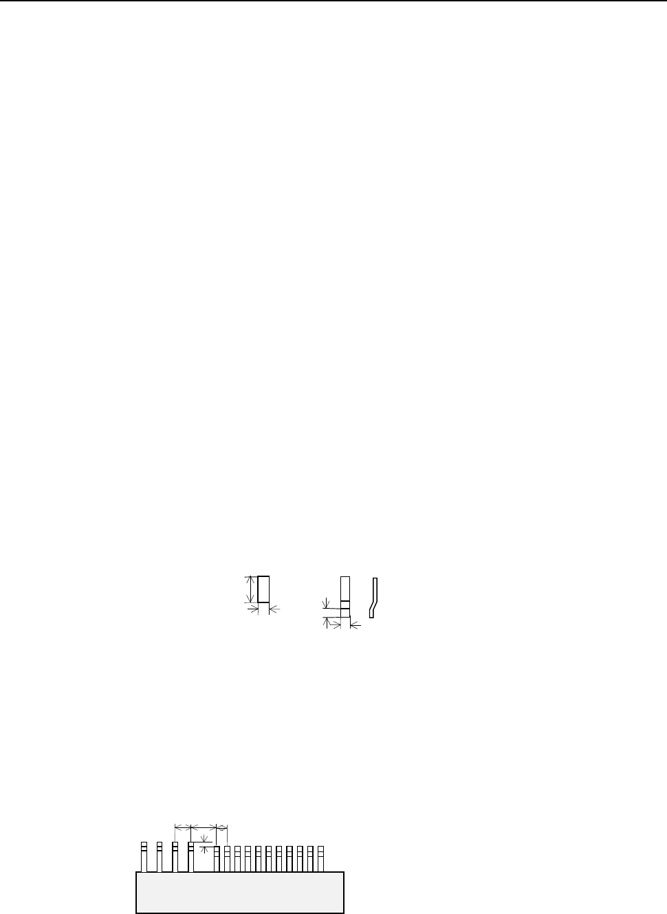
3. Lead components
- At least one element group including two or more leads has to exist on a component.
- As the lead size, the ratio of the length to width should be 1 or more. For a gull-wing lead,
the ratio of the length to the length specified in the “Lead size” should be 1 or more.
Length
Length
Width
Width
Normal lead
Gull-wing lead
The length of a lead
should be longer than
the width.
- When a lead end (lead end position) of one lead element group is laterally located near
another lead element group, whose lead end height is almost the same with that of the former
lead element group (that is, the height difference should be 0.5 times of the pitch or less), the
centers of the adjacent two leads should be located far from one another by two times of the
pitch. For an element group that has only one lead, the center of one group should be far
from that of another one by two times of the lead width. If a lead-like shaped substance is
located near a lead, they should be far from one another in the same manner.
P1
P2
L
H
<TOP VIEW>
P1: Pitch of Element group 1
P2: Pitch of Element group 2
L: Distance between two element groups
H: Difference between lead ends of two
element groups
H ≦ 0.5 P1 and H ≦ 0.5 P2
L ≧ 2P1 and L ≧ 2P2
- If another lead group is located in the longitudinal direction of a lead of one lead group, it
should be far from the lead by the distance equal to the lead width and at least by 1 mm.