RS-1_instruction manual.pdf - 第59页
Part 1 B asic O peration Chapter 1 Overv iew of the Machine 1- 41 Component nam e Lead pitch/(s ize) Component siz e Remar ks Q F P, B Q F P, QFN Pitch: 0.65/0.8/1.0mm (Note 1) BGA Pitch: 1.0 mm or more, and less than 2.…

Part 1 Basic Operation Chapter 1 Overview of the Machine
1-40
(4) Applicable components
1) Laser recognition
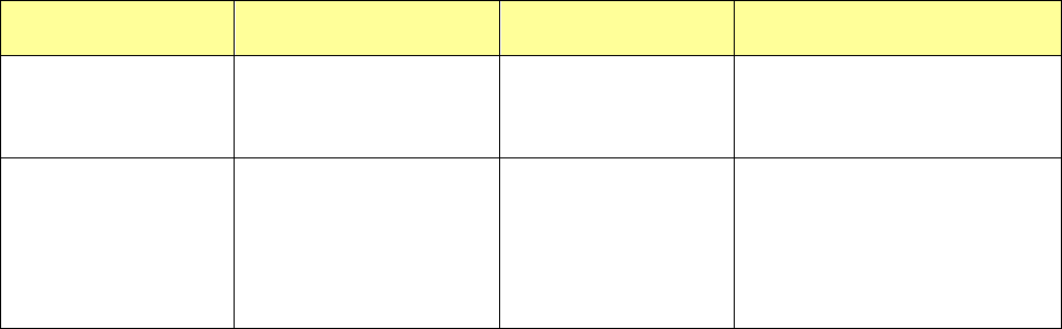
Component name Lead pitch/(size) Component size Remarks
Square chip resistor
03015, 0402, 0603,
1005, 1608, 2012, 3216,
3225, 5025, 6432
Note: If a 03015 component cannot be
recognized with laser stably due to its
shape (for example, if a string art image
is not displayed normally), use a VCS
(10-mm field of view camera) (optional).
Network resistor
(Excluding an SOP, SOJ
and PLCC types)
MELF resistor
1.6×φ1.0, 2.0×φ1.25,
3.5×φ1.4, 5.9×φ2.2
Laminated ceramic
capacitor
0402, 0603, 1005, 1608,
2012, 3216, 3225, 4532,
5750, 5632
Tantalum chip capacitor 3216, 3528, 6032, 7343
Aluminum electrolytic
capacitor
Lead width:
0.2 mm to 3.5 mm
Height: 6.0 or less
Height: More than 6.0
to 10.5 mm
GaAsFET
Lead width:
0.2 mm to 3.5 mm
Chip film capacitor
6.5 x 4.5 x 2.7 to
10.5 x 7.2 x 5
Variable trimmer
capacitor, Chip
potentiometer, trimmer
Chip ferrite bead
1005, 1608, 2012, 3216,
3225
Cylindrical shape
Chip inductor
1005,1608,
2012,3216,3225
SOT
Mold section 1608/2012
SOT-23, SOT-89,
SOT-143, SOT-223
SOP, TSOP, HSOP
Pitch
0.65/0.8/1.0/1.27mm
(Note 1)
SOJ Pitch 0.65/1.27mm
PLCC Pitch 1.27mm
Part 1 Basic Operation Chapter 1 Overview of the Machine
1-41
Component name Lead pitch/(size) Component size Remarks
Q F P,
B QF P,
QFN
Pitch:
0.65/0.8/1.0mm
(Note 1)
BGA
Pitch: 1.0 mm or more, and
less than 2.0 mm
(when zigzag alignment: 3.0
mm or less)
(Ball diameter: 0.4 mm or
more, and 1.0 mm or less)
(Note 3)
Note 1: Even a component whose lead pitch is regulated respectively such as a QFP can be recognized
with a pitch not described above.
(This machine shall be able to recognize a pitch not described in the table above with considering
variation in lead pitches.) In such a case, a pitch within a range of the minimum one to the
maximum one can be recognized. Note that a pitch from 0.38 mm can be recognized if the
minimum pitch is 0.4 mm.
Note 2: The size of a component that can be recognized varies depending on a nozzle to be used.
The No. 1 and No. 8 nozzles can be applied to up to ☐20 mm (See Note 6), No. 2 and 7 nozzles
can be applied to up to ☐35 mm, and the No. 3, 4, 5 and 6 nozzles can be applied to up to ☐50
mm.
Note 3: Since the external shape of a component is recognized with laser of the LNC120-8, any component
cannot be placed on a board with regarding a lead or a ball as the reference position.
Part 1 Basic Operation Chapter 1 Overview of the Machine
1-42
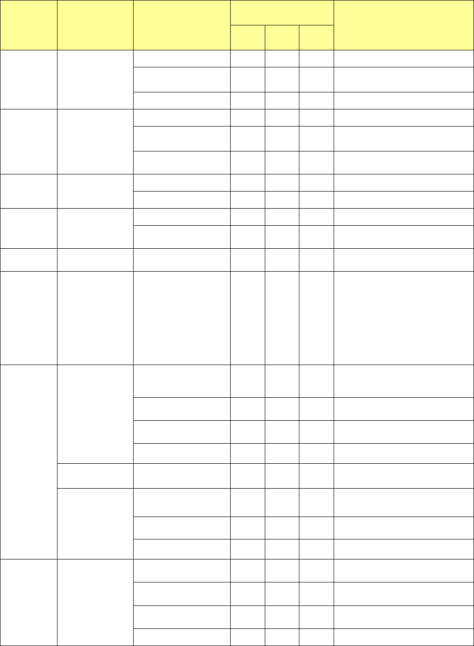
2) VCS recognition
○ : Recognition target components, ◎ : Recognizable without
stopping, △: Image dividing recognition (available with the 3-nozzle
head only), ●: Not recommended due to increase in the cycle time
Component
name
Lead pitch/(size) Component size
Recognition with a VCS
(See Note 3)
Remarks
54mm
VCS
27mm
VCS
10mm
VCS
Square chip
resistor
03015, 0402, 0603
●
1005, 1608, 2012,
3216, 3225, 5025
― ● ●
6432
● ● ●
Laminated
ceramic
capacitor
0201, 0402, 0603
●
1005, 1608, 2012
3216, 3225
― ● ●
4532, 5750, 5632
●*1 ● ●
*1: Not available for a component
whose size is
□
3 mm or less
Tantalum
capacitor
3216, 3528,
― ● ●
6032, 7343
● ○◎ ●
Aluminum
electrolytic
capacitor
Lead width:
0.12 mm to 1.5 mm
6.0mm or less (height) ○ ○◎ ○
More than 6.0mm、(height)
10.5mm or less
○ ○◎ ○
GaAsFET
Lead width:
0.12 mm to 1.5 mm
○
○◎
*3
○
Variable
trimmer
capacitor, chip
potentiometer,
trimmer
○*2 ― ○*3
*2: Not available for a component
whose size is □3 mm or less.
*3: To recognize a resistor chip, a
trimmer, an SOT or an LED
whose size is 1.0×
0.5 to 3 mm,
use an optional 27 mm view
camera to recognize such a
component as a general-purpose
vision component.
S OP,
T S O P,
HSOP
Pitch:
0.4/0.5/0.65
/0.8/1.0/1.27mm
More than □33.5 mm,
and □50 mm or less
○ △*4 △*4
*4: Neither an HSPO image nor a QFN
image can be divided to be
recognized.
More than □24 mm, and
□
33.5 mm or less
○*5
●
△*4
△*4
*5: □33.5 mm or less.
More than □20 mm, and
□
24 mm or less
○ ●◎
●
△
*4
□20 mm or less
○ ●◎
●
△
*4
Pitch:
0.5/0.65mm
26mm ×11.5mm
○ △*4
●
△*4
Pitch:
0.2mm
More than □24 mm, and
□34 mm or less
―
○
△*4
△*4
More than □20 mm, and
□
24 mm or less
― ○◎
○
△*4
□20 mm or less
― ―
○
△
*4
SOJ
Pitch:
1.27mm
More than □33.5mm, and
□50 mm or less
○
― ―
More than □24 mm, and
□
33.5 mm or less
○ *5
●◎ ―
*5: □33.5 mm or less.
More than □20 mm, and
□24 mm or less
○
●◎ ●
□20 mm or less ○
●◎ ●