RS-1_instruction manual.pdf - 第47页
Part 1 B asic O peration Chapter 1 Overv iew of the Machine 1- 29 Others (1) Automati c tool cha nger (A TC) The ATC can accommod ate up to 45 noz zles. W hen a la rge - si zed noz zle is supported, the ATC c an accommod…
Part 1 Basic Operation Chapter 1 Overview of the Machine
1-28
Note 1: The described angle of a 0402 component shall be applied only if the XY positioning accuracy is
±0.040 mm and an IC is placed in the two-thirds or larger area of the pad whose width is 0.2 mm.
Note 2: Notes on recognition with laser are the same as those on the machine position (XY).
Note 3: The general-purpose vision component placement accuracy widely varies depending on the
component characteristics and/or lighting conditions.
Example: The placement accuracy of a 1005 resistor chip becomes ±3°(3σ) if it is recognized as a
general-purpose vision component. You have to pay attention to the following points:
- Turn off the coaxial light, and set the brightness of the red side light and bottom light to a
higher value to adjust the lights so that any nozzle cannot be shot with the VCS.
- The dedicated nozzle may be required depending on the light reflection characteristics of a
component.
Note 4: The component placement accuracy to be applied when a component is recognized with laser,
and then its position is corrected shall be an absolute value from a component reference mark or
board reference mark too.
Note 5: When a component consists of two or more parts such as a BGA socket, the parts shall not rattle.
If any of them rattles, the component placement accuracy cannot be guaranteed.
Part 1 Basic Operation Chapter 1 Overview of the Machine
1-29
Others
(1) Automatic tool changer (ATC)
The ATC can accommodate up to 45 nozzles.
When a large-sized nozzle is supported, the ATC can accommodate up to 38 nozzles.
(2) Transport rail height
900 mm ± 20 mm (For Japan, China and southeastern Asian countries models)
950 mm ± 20 mm (For the U.S.A. and Europe models)
(3) Air requirements
Air pressure: 0.5 ± 0.05 Mpa
Maximum air consumption: Vacuum pump 50 L/minute (standard condition), Ejector 200
L/min (standard condition)
Dry air: Dew point under pressure 10 °C or less (Oil and dust shall be
removed appropriately.)
* The following organic solvents and chemicals will deteriorate the polycarbonate resin of the
air combination case unit. Do not use them.
Type
Chemical name
Acid:
Hydrochloric acid, phosphoric acid sulfate, chromic acid
Alkali:
Caustic soda, caustic potash, slaked lime, ammonia water, sodium carbonate
Inorganic salt:
Soda sulfide, potassium nitrate, soda nitrate
Chlorine solvent:
Carbon tetrachloride, chloroform, ethylene chloride, methylene chloride
Aromatic type:
Benzene, cyclohexane, thinner
Ketone type:
Acetone, methyl ethyl ketone, cyclohexane
Alcohol type:
Ethyl alcohol, IPA, methyl alcohol
Oil type:
Gasoline, kerosene, water-soluble cutting oil (alkaline)
Ester type:
Dimethyl phthalate, diethyl phthalate
Ether type:
Methyl ether, ethyl ether
Amine:
Methyl amine
Others:
Screw lock liquid, salt water, leak taster
(4) Noise level: 73 dB (A) or less
(5) Country of manufacturing: Manufactured in Japan
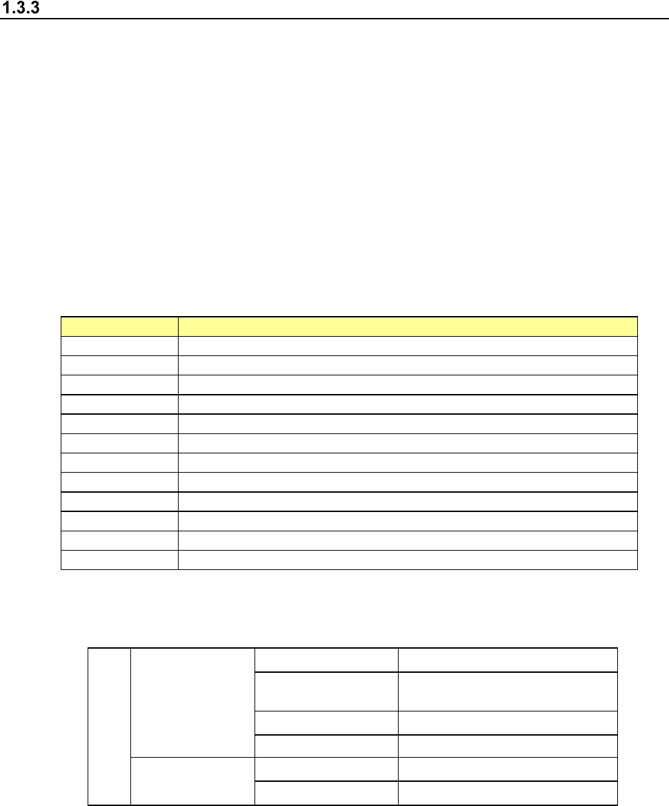
(6) Environmental conditions
Environment requirements
During operation
Temperature 10℃ to 35℃
Accuracy guaranty
temperature
22℃ to 25℃
Humidity
50%RH or less (35℃)
Altitude 1000m or less
Transportation or
storage
Temperature -15℃ to 70℃
Humidity 20 to 95%RH (No condensation)
(7) Installation conditions
Overvoltage Category: Category III (IEC60664-1)
Pollution Degree: Degree 3 (IEC60664-1)
Part 1 Basic Operation Chapter 1 Overview of the Machine
1-30
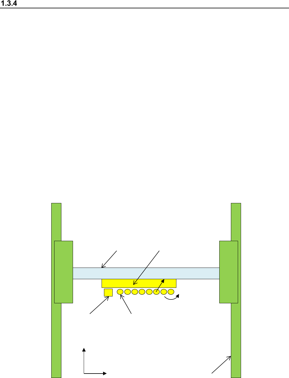
X, Y, Z, ZA, and θ axes descriptions
The following four axes (X, Y, Z, and θ) are numerically controlled in this machine.
(1) X- and Y-axis
The X-axis represents the left and right directions of the machine, while the Y-axis represents
the front and rear directions: a position is given as X = xxx.xx mm and Y = xxx.xx mm in
increments of 0.01 mm. Two coordinate systems are available:
one given by the production program and another given by teaching operation.
Both coordinate systems are automatically changed, so you do not have to switch
the coordinate system by yourself.
(2) Z-axis
The Z-axis represents the height direction of a nozzle, given as Z = xx.xx mm, in 0.01-mm
increments.
The upward direction is positive (+), with the top side of a board clamped (any jig is not used)
being 0.
(3) θ-axis
The q-axis represents the rotation angle of the head, given as "A = xx.xx" (in 0.05 increments.)
The value is positive for counterclockwise rotation and negative for clockwise rotation.
(4) ZA-axis
The ZA-axis represents the height direction of the LNC120 sensor, given as Z = xx.xx mm, in
0.01-mm increments.
The upward direction is positive (+), with the top side of a board clamped (any jig is not used)
being 0.
X-axis
Y-axis
Head
Y+
X+
Z+
θ
+
OCC
L1 nozzle shaft
L1 to L8 from left to right