RS-1_instruction manual.pdf - 第51页
Part 1 B asic O peration Chapter 1 Overv iew of the Machine 1- 33 ① ② ① Left side of the fr ont of the main unit (X L) Right side o f the front of the m ain unit ( XL) List of connect ors on the left side pa nel No. Sign…
Part 1 Basic Operation Chapter 1 Overview of the Machine
1-32
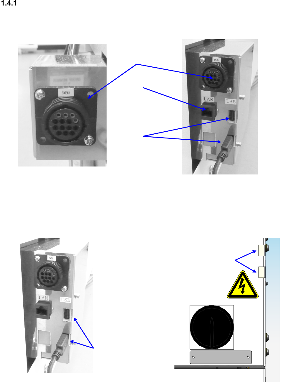
Interface with external devices
① is a SMEMA connector. To use the main unit online and connect it to another device, the board
transport direction, “left to right” or “right to left,” of both should be the same with each other.
② is an Ethernet connector (8-pin modular connector).
Left side of the front of the main unit
Right side of the front of the main unit
③ are USB connectors (two). In and before Rev. C system, this item is installed in the same
position as ② in the lower right side of the front. In and after Rev. D system, it is installed on
the power switch in the right side of the front.
(If you use a flash-memory device, be sure to remove it after finishing operating the machine.)
Right side of the front of the main unit
(in and after Rev. C)
Right side of the front of the main unit
(in and after Rev. D)
③ (In and before Rev. C)
①
②
③
③ (In and after Rev. D)
Part 1 Basic Operation Chapter 1 Overview of the Machine
1-33
①
②
①
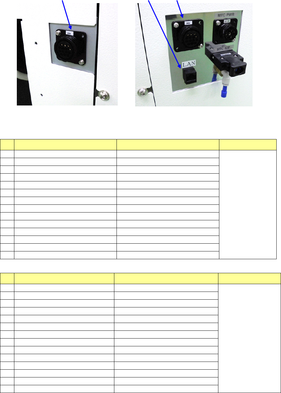
Left side of the front of the main unit (XL)
Right side of the front of the main unit (XL)
List of connectors on the left side panel
No.
Signal name (left to right) Signal name (right to left) Connector used
1
READY OUT
+
READY IN
+
AMP
206043-1
Connection of
the cable end
206044-1
2
READY OUT
-
READY IN
-
(GND)
3
BOARD AVAILABLE IN
+
BOARD AVAILABLE OUT
+
4
BOARD AVAILABLE IN
-
(GND)
BOARD AVAILABLE OUT
-
5
N.C.
N.C.
6
N.C.
N.C.
7
N.C.
N.C.
8
N.C.
N.C.
9
N.C.
N.C.
10
N.C.
N.C.
11
N.C.
N.C.
12
N.C.
N.C.
13
N.C.
N.C.
14
N.C.
N.C.
List of connectors on the right side panel
No.
Signal name (left to right) Signal name (right to left) Connector used
1
READY IN
+
READY OUT
+
AMP
206043-1
Connection of
the cable end
206044-1
2
READY IN
-
(GND)
READY OUT
-
3
BOARD AVAILABLE OUT
+
BOARD AVAILABLE IN
+
4
BOARD AVAILABLE OUT
-
BOARD AVAILABLE IN
-
(GND)
5
N.C.
N.C.
6
N.C.
N.C.
7
N.C.
N.C.
8
N.C.
N.C.
9
N.C.
N.C.
10
N.C.
N.C.
11
N.C.
N.C.
12
N.C.
N.C.
13
N.C.
N.C.
14
N.C.
N.C.
Part 1 Basic Operation Chapter 1 Overview of the Machine
1-34
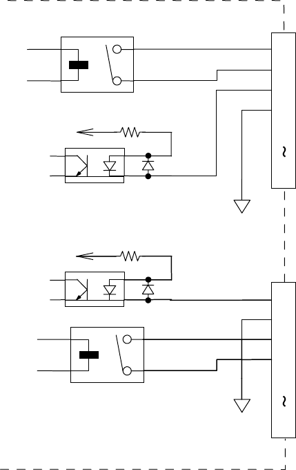
◇ The following figure shows the interface circuits for READY OUTs (IN) and BOARD AVAILABLE
signals.
They conform to the SMEMA standard.
GND(24V)
+
+
24V_
3.3K 1/4W
READY OUT +
BOARD AVAILABLE IN +
READY OUT -
BOARD AVAILABLE IN -
N.C.
1
2
3
4
5
14
READY IN +
BOARD AVAILABLE OUT +
READY IN -
BOARD AVAILABLE OUT -
N.C.
1
2
3
4
5
14
+
24V_
3.3K 1/4W
+
GND(24V)