RS-1_instruction manual.pdf - 第286页
Part 1 B asic O peration Chapter 2 Pr oduction 2- 175 If you are to replace a feeder bank with another one during produc tion (1) C heck t o see if the f eeder bank to be r eplaced w ith anot her one is disa bl ed. If it…
Part 1 Basic Operation Chapter 2 Production
2-174
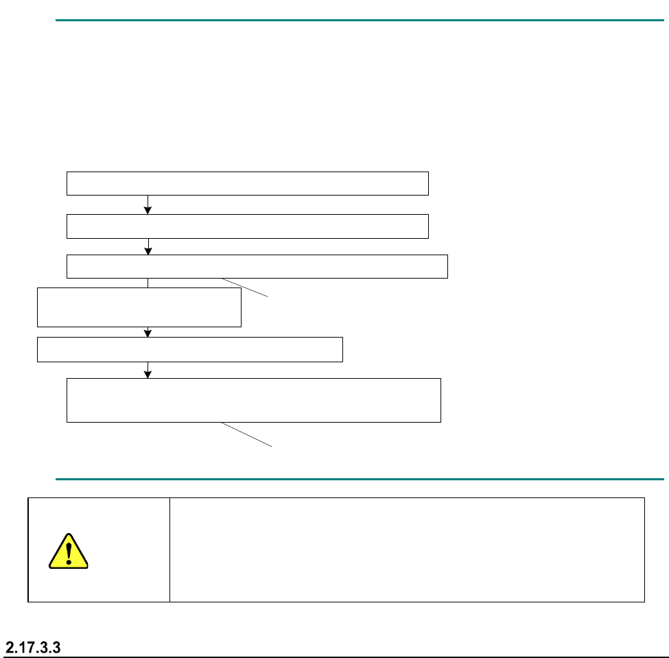
For example, if you disable the feeder bank while a component is being picked up, you may have
to stop picking up the component from the corresponding feeder bank immediately.
In such a case, the feeder bank from which the next component will be picked up is changed to
the enabled one after the component(s) already picked up is (are) placed on a board.
- Example: When components are placed after two components are picked up
1点目の部品吸着(マスタ側のフィーダバンクからの吸着)
このタイミングではスレーブ側には切り替わりません
このタイミングからスレーブ側からの吸着となります
マスタ
側のフィーダバンクを無効化
2点目の部品吸着(マスタ
側のフィーダバンクからの吸着)
1点目の部品搭載
2点目の部品搭載
次シーケンス
1点目の部品吸着(スレーブ
側のフィーダバンクからの吸着)
CAUTION
Even though the feeder bank is moved down during production in
Non-stop operation mode, a head(s) move(s) at high speed when a
feeder bank on one side is enabled.
Never put your hand or face in the machine or move it closer to the
machine.
When components run out
The mini signal lamp corresponding to the feeder bank on which components run out lights, and the
feeder bank is disabled.
When you detach the feeder bank, set it on the machine again, and then enable it, the
corresponding mini signal lamp goes off.
Note that this mini signal lamp works also as an indicator for indicating that the corresponding
feeder bank is set on the machine correctly. Therefore, if you fail to set the feeder bank on the
machine normally, the corresponding mini signal lamp remains lit even though you enable the
feeder bank.
Even though you enable the feeder bank without detaching the feeder bank while the mini signal
lamp is lighting, the mini signal lamp goes off.
Pick-up of the first component (from the master feeder bank)
Disabling of the master feeder bank
Pick-up of the second component (from the master feeder bank)
Placement of the second component on a board
Next sequence
Pick-up of the first component (from the slave feeder bank)
Components are picked up from the slave feeder
bank at this point.
The feeder bank for picking up a component is not
switched to the slave feeder bank at this point.
Placement of the first component
on a board

Part 1 Basic Operation Chapter 2 Production
2-175
If you are to replace a feeder bank with another one during production
(1) Check to see if the feeder bank to be replaced with another one is disabled. If it is enabled,
disable the bank on the corresponding side (front/rear).
(2) Check to see if components are picked up from the feeder bank on the opposite side. Check
to see if at least one component is picked up and at least one component is placed on a board
already.
(3) Detach the feeder bank from the machine.
(4) Set the feeder bank for replacement on the machine.
(5) If the feeder bank set on the machine is the same as the bank specified in the production
program which is being used for the current production, press the <Feeder Bank Enable>
switch to enable the feeder bank.
If you are to perform changeover of the master feeder bank during production
(1) Check to see if the master feeder bank is disabled. If the master feeder bank is enabled,
disable it.
(2) Check to see if components are picked from the slave feeder bank. This operation is required
because component pick-up operation cannot be switched to the slave feeder bank
immediately after the master feeder bank is disabled.
(3) Detach the master feeder bank from the machine.
(4) After changeover of the feeder(s), set the feeder bank on the master side of the machine.
(5) When changeover is performed (a production program is switched to another one), enable the
master feeder bank. In Alternate production mode, enable the master feeder bank before
switching the programs. If you enable the master feeder bank after switching a production
program to another one, components are picked up from the sub feeder bank, and then this
may cause a component to be placed at a wrong position.
(6) Press the Start switch to pick up components from the master feeder bank.
When the system is not put in Alternate production mode, priority is given to the master feeder
bank even though the slave feeder bank is enabled. Therefore, components are not picked up
from the sub feeder bank unless the master feeder bank is disabled.
If you are to perform changeover of the salve feeder bank during production
(1) Disable the slave feeder bank.
(2) Check to see if components are picked up from the master feeder bank. This operation is
required because components may run out on the master feeder bank depending on when the
slave feeder bank is disabled, so that components may be picked up from the slave feeder
bank.
(3) Detach the slave feeder bank from the machine.
(4) After changeover of the feeder(s), set the feeder bank on the slave side of the machine.
(5) Enable the feeder bank on the slave side after the system finishes producing the planned
number of PWBs and the machine stops.
(6) Switch the production program to another one, and disable the master feeder bank.
(7) If you start production when the front side is specified as the master feeder bank, the front
feeder bank is disabled and the rear feeder bank is enabled, the message “No completion
change plan. Please use Feeder Bank.” appears on the screen. When you clear this
message and then press the Start key of the panel switches, components start being picked up
from the rear feeder bank.
(8) When you set the master feeder bank on the machine after changeover of the master feeder
bank and then enable the mater feeder bank, components are picked up from the master
feeder bank. However, when the system is put in Alternate production mode, components
keep being picked up from the slave feeder bank.

Part 1 Basic Operation Chapter 2 Production
2-176
When you perform the operation described in Step (8) before performing that in Step (7), the
message described above does not appear on the screen, and the system performs production
from the master bank.
When components run out
(1) Check to see if any component is not picked up from the feeder bank at which components run
out.
The mini signal lamp corresponding to the side on which components run out is lighting, and
the feeder bank is disabled.
(2) Since the feeder bank is disabled, detach it from the machine.
(3) Replace the feeder at which components run out with another one, and then attach the feeder
bank on the machine.
(4) Enable the feeder bank.
Batch feed function during Non-stop operation
If any component such as a chip component is exposed when you set a feeder on the machine, it
may be turned over due to shock given to it when the bank moves up. Therefore, the system
provides you with the function for feeding all feeders attached on the bank forcibly when the banks
is enabled.
Since the number of electric feeders that can be fed at a time is limited, feeding operation is
performed repeatedly for the certain number of electric feeders.
The bank is not enabled until all feeders finish being fed.
After knocking of all feeders finishes, the bank is enabled, and the system permits a component to
be picked up from each feeder.
When the system consists of an RF type feeder and an EF type feeder
When the same type components are prepared on both the front side and the rear side, the
Non-stop Operation function normally picks up a component from the master bank, and the slave
feeder bank is to be used as the auxiliary component supply source only when the master bank is
refilled with components (except when the system performs alternate production).
Therefore, if at least one component of the same type is prepared at each of the front and rear
feeders, the system can perform Non-stop operation.
The RS-1/1R machine can use an RF type electric feeder and an EF type electric feeder. Since
the same type of components can be supplied by both feeders, even when both an RF type feeder
and an EF type feeder are used on the front side and the rear side respectively, the system can
perform Non-stop operation. However, the non-stop operation feeder layout cannot be created
with the [Feeder Layout] command or the Optimization function in such a case. Then, you have to
assign the components specified for a feeder attached on the master feeder bank to a feeder on the
slave feeder bank manually, and produce a PWB in input order.
In addition, the number of electric feeders you can return to their respective home positions at a
time is limited in the same manner as that of feeders you can feed at a time. Therefore, in the
same manner as the batch feeding function, enable the bank, and then perform the zero-return
operation repeatedly for the certain number of electric feeders. The system does not enable the
bank until the feeders become able to supply the machine with components. Only after all of the
feeders finish returning to the respective home positions and become able to supply the machine
with components, the system enables the bank, and then permits components to be picked up from
these feeders.