RS-1_instruction manual.pdf - 第636页
Pa r t 2 D et ai l ed Des c r i pt i o n of Ea c h F unc t i o n Chapte r 6 G e neral - Purpose Vision Co mpone nt 6-5 Creatin g an Elemen t group/Elem ent f orma t 6.2.1 W hen you t ouch t he < Add> b utton o n th…
Part 2 Detailed Description of Each Function Chapter 6 General-Purpose Vision Component
6-4
Data Entry Items 6.2
When a component is set as a general-purpose component on the “Component” data screen, the
<Element > button appears on the “Form” screen invoked from the “Vision” data screen.
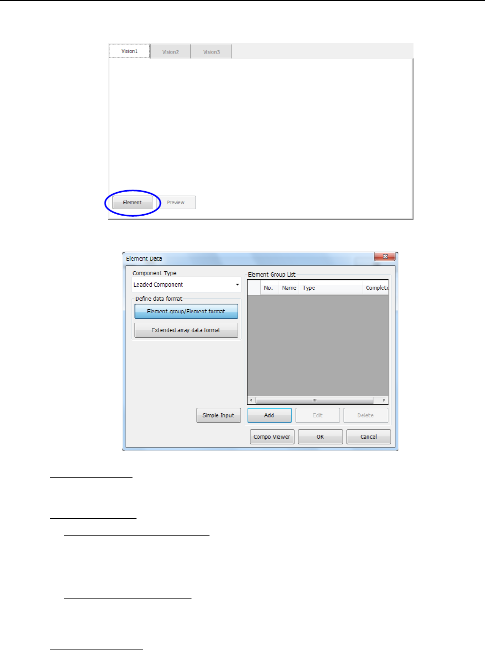
When you touch the <Element > button, the following “Element Data” screen appears.
• Component Type:
Select a component type among a lead component such as a QFP, a ball component such as
a BGA and an outline recognition component.
• Define data format
− Element group/Element format:
Checking this check box allows you to specify an element to be recognized such as a lead
and ball, define the element group (consisting of the same elements); pitch and quantity,
and specify the orientation and position of the group. Check this box when you are to
create data on a “multi-lead component” or “complex array component.”
− Extended array data format:
Checking this check box allows you to define data by specifying the X and Y coordinates of
an element to be recognized such as a ball or land one by one. Check this box when you
are to create data on a “random component.”
• Element Group List:
The element group you created appears here.
To create a new element group, touch the <Add> button.
To edit the existing element group, touch the <Edit> button.
Part 2 Detailed Description of Each Function Chapter 6 General-Purpose Vision Component
6-5
Creating an Element group/Element format 6.2.1
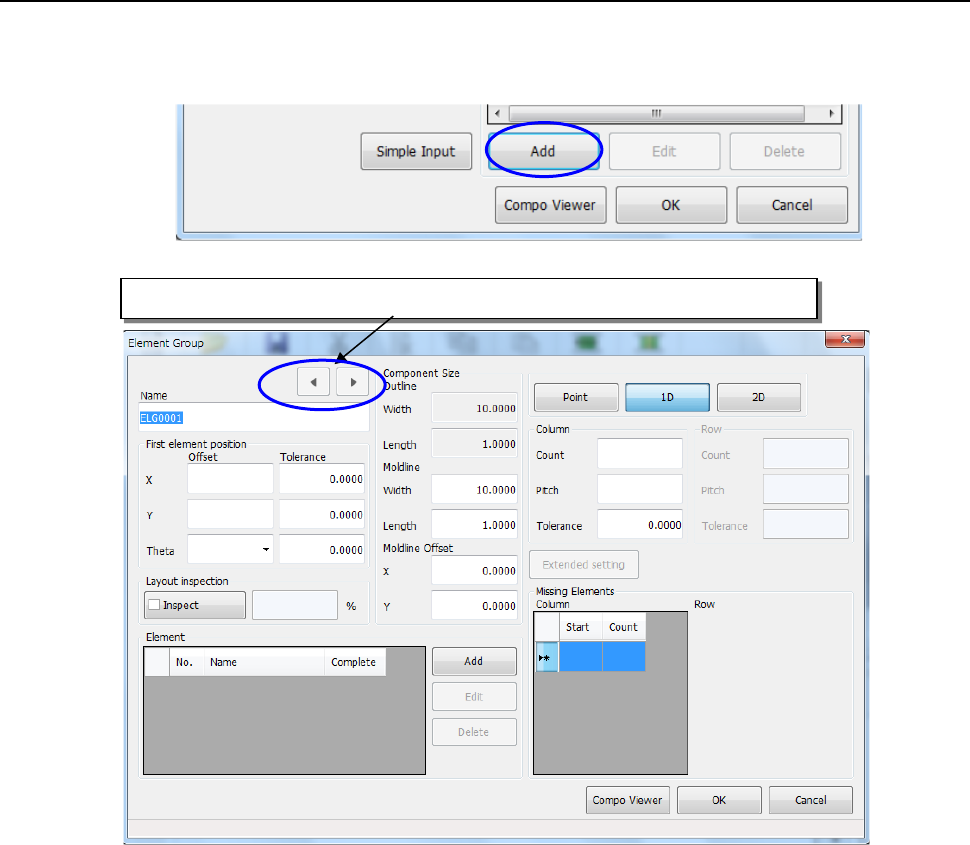
When you touch the <Add> button on the “Element Data” setting screen, the “Element Group”
creation screen appears.
(1) Name:
Enter up to 32 alphanumeric characters to specify the name of an element group.
(2) First element position:
Enter the distance between the center of a component to be recognized and the first
element.
• Offset
− X, Y: For a multi-lead component, enter the distance between the component center
position and the center of the tip of the first element. For a complex-array
component, enter the distance from the component center position to the center
of the first element.
* Be sure to enter the dimensions correctly. If an error of the distance
between element groups exceeds ± 0.05 mm, the system may not recognize
the element groups.
− Theta: Enter this field for a multi-lead component only. When a lead is located on the
bottom side, enter “0°.” For the right side, enter “90°,” for the top side, enter
“180°” and for the left side, enter “270°.”
• Tolerance:
Although you can specify the tolerable range of value to be set, do not change the
initial value “0.” Be sure to use “0” for all “Tolerance” fields of the element group.
Clicking either of these buttons displays the previous or next element group data.
Part 2 Detailed Description of Each Function Chapter 6 General-Purpose Vision Component
6-6
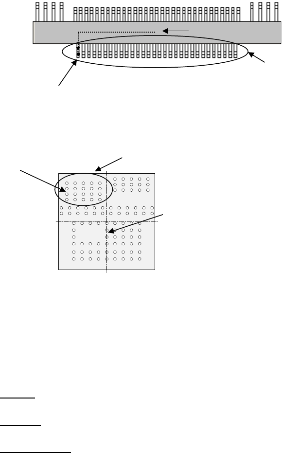
Example 1: Multi-lead component
Example 2: Complex-array component
3) Layout inspection
Set the tolerant range in which the center can be shifted with considering a lead pitch or ball
pitch.
4) Component Size
When you enter data to these fields for a lead component, the system can open the
Component Viewer (see Section 6.3) correctly.
• Outline:
Values entered on the “Component” data screen appears here.
• Moldline:
Enter the dimensions of the molded section of a component.
• Moldline Offset:
When you enter data to the “Moldline” and “Moldline Offset” fields, the system can display
a lead component more correctly. This function is provided for the Component Viewer
only. If you do not enter any value to these fields, the dimensions of a component
appear on the Component Viewer screen.
5) Point, 1D, 2D
• Point : Select this radio button if there is only one element in the element group.
• 1D : Select this radio button for a component such as a lead component whose
elements are placed in a line.
• 2D : Select this radio button for a component such as a BGA whose elements are
placed horizontally and vertically.
6) Column, Row
When you select the radio button “1D” or “2D,” enter the number of leads or balls, and the
pitch.
Bottom View
部品中心位置
(
外形中心位置)
First element position (Θ = 0º)
Element group
Center of a component
to be recognized
First element position
Element group
Center of a component to
be recognized