RS-1_instruction manual.pdf - 第657页
Pa rt 2 Detailed Des cription o f Each Function Chapter 6 G eneral - Purpose Visio n Component 6- 26 (2) Adding an ele ment group (3) Deleting an ele ment grou p When you touch the <OK > button, the system creat es…
Part 2 Detailed Description of Each Function Chapter 6 General-Purpose Vision Component
6-25
How to create data on an outline recognition component 6.4.4
You can enter data on an outline recognition component (only “corner” or “side” element) with
Simple Input.
Note that all element groups should be at a corner or side, and the maximum number of element
groups is “4.”
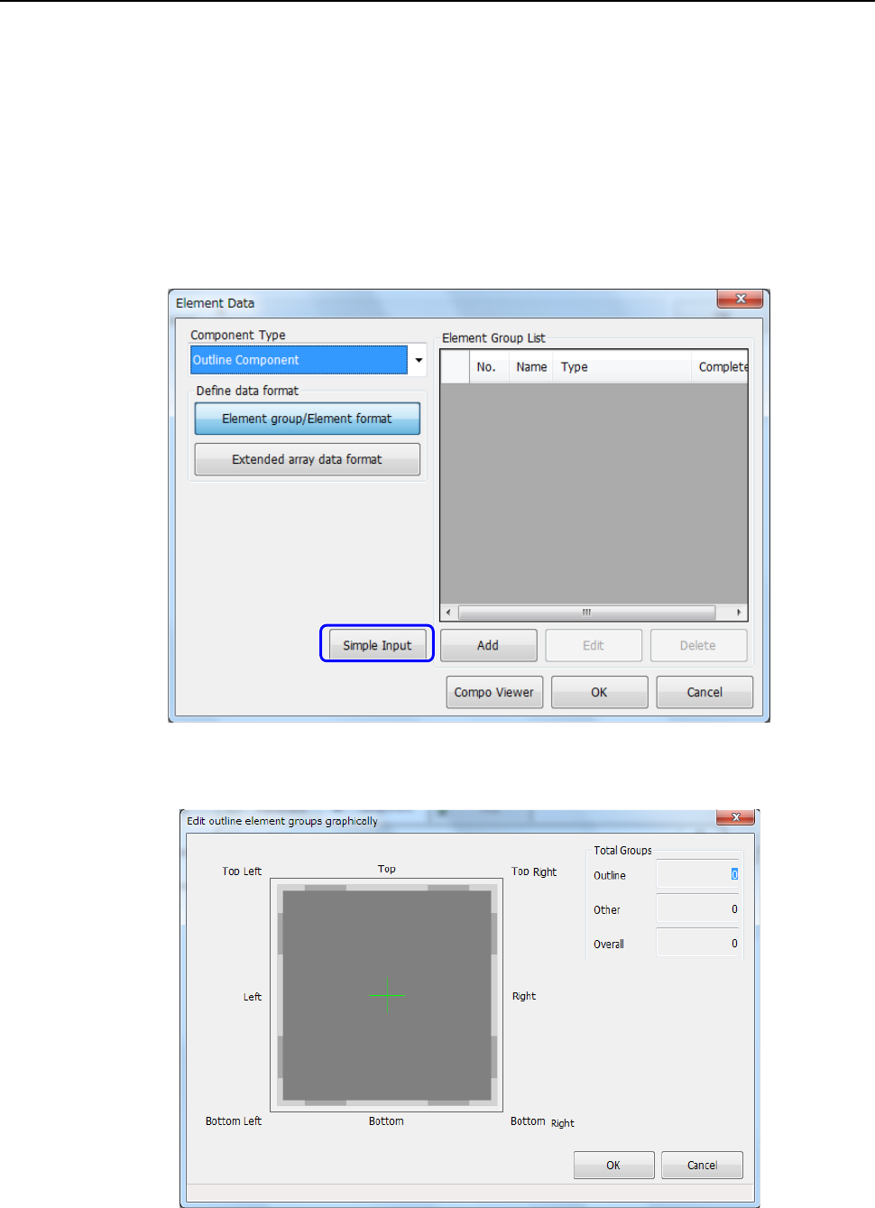
(1) Starting up the “Edit outline element groups graphically” dialog box
① Select “Outline component” in the “Component Type” field on the “Element Data” screen,
and click the <Simple Input> button.
② The “Edit outline element groups graphically” dialog box appears on the screen.
Part 2 Detailed Description of Each Function Chapter 6 General-Purpose Vision Component
6-26
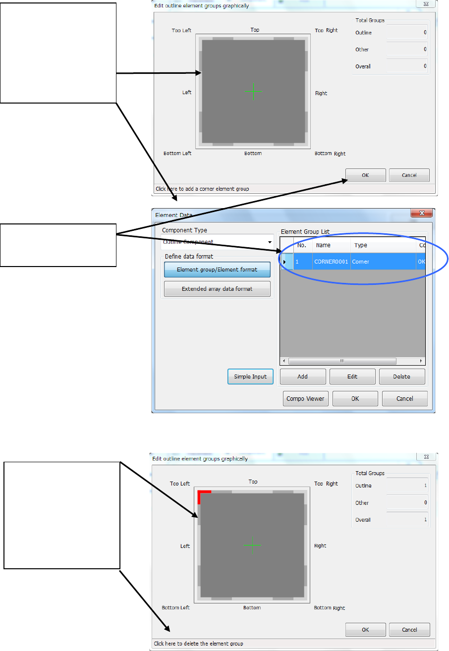
(2) Adding an element group
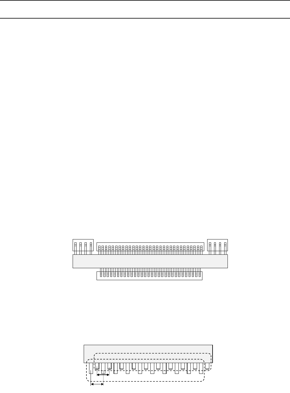
(3) Deleting an element group
When you touch the <OK>
button, the system creates
an element group.
When you place the mouse
pointer at the position
around the corner or side
where you can delete an
element group, the mouse
pointer changes to the
hand-shaped cursor and the
message appears on the
bottom of the dialog box.
Touch this position.
When you place the mouse
pointer at the position
around the corner or side
where you can add an
element group, the mouse
pointer changes to the
hand-shaped cursor and the
message appears on the
bottom of the dialog box.
Touch this position.
Part 2 Detailed Description of Each Function Chapter 6 General-Purpose Vision Component
6-27
Procedure for creating general-purpose vision component data 6.5
Lead components (Element group/Element format) 6.5.1
This section describes the procedure for creating data on lead components (multi-lead
components).
1. Operation on the “Element Data” screen
- Select “Lead Component” on the “Component Type” combo box.
- Check the “Element group/Element format” check box in the “Define data format” field.
- Click the <Add> button on the “Element Group List.”
2. Operation on the “Element Group” screen
Define an element group on this screen.
An element group is composed of components whose lead size and pitch are the same.
•
Description
In the example below, four element groups are defined. The size and pitch of leads of the
first and third element groups are the same, while the direction and position of leads of these
groups are different from each another. The size and pitch of leads of the second and
fourth element groups are the same also, but leads of these groups are not arrange
continuously, so the lead pitch is not the same. If the distance between these leads is an
integral multiple of the specified pitch, they can be defined as one element group that has an
area having no lead. However, we recommend that you define them as separate element
groups.
To define the direction and position of the element group, specify the component posture.
The direction of a component shown in the figure below shall be normal. The posture of
multi-lead components is regulated from the top view.
If the length of a lead changes alternatively as shown in Figure define two groups: one having
long leads and another having short leads. The pitch is also defined for a group of long leads
and that of short leads separately.
Fourth element
group
Third element
group
Second element
group
First element
group
Top View
First element group
Pitch 2
Pitch 1
Second element group