RS-1_instruction manual.pdf - 第646页
Pa r t 2 D et ai l ed Des c r i pt i o n of Ea c h F unc t i o n Chapte r 6 G e neral - Purpose Vision Co mpone nt 6- 15 Exam ple of “ Com ponent V iewer ” screen w hose conten ts vary dep endin g 6.3.3 on th e elemen t …
Part 2 Detailed Description of Each Function Chapter 6 General-Purpose Vision Component
6-14
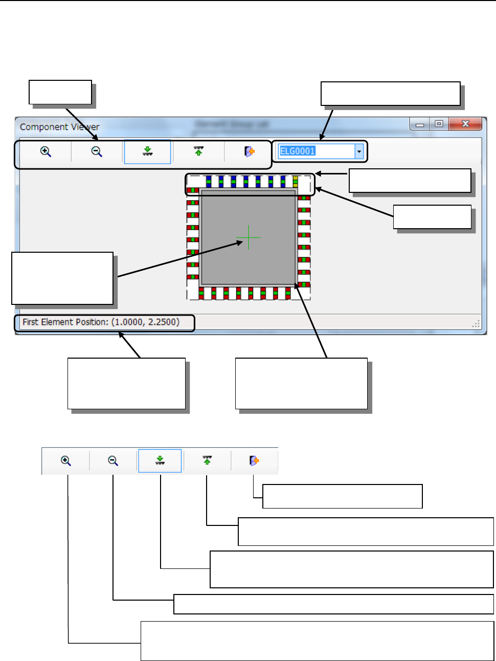
How to use “Component Viewer” 6.3.2
Select an element group from the “Element Group List” or click the element group you want to
select with a track ball. The selected element group is displayed in blue, and its first element is
displayed in yellow.
■ Tool bar
*1 If you use the Component Viewer to display the element defined on the top side so that it can be
viewed from the bottom side, or the element defined on the bottom side so that it can be viewed
from the top side, the element may become invisible.
Coordinates of the first
element of the selected
element group
Selected element group
First element
Tool bar
Element group selection list
Cross line
representing the
center of component
Component shape entered
on the "Component" data
screen(including leads)
Zoom Out: Scales down the component size 10% by clicking the icon.
Zoom In: Displays the icon in the pressed status by clicking the icon.
When you click it with the mouse left-button on the screen, the
component size is scaled up 10%.
End: Closes the Viewer.
Top View: Displays a figure of the component viewed
from the top. *1
Bottom View: Displays a figure of the component viewed from
the bottom. *1
Part 2 Detailed Description of Each Function Chapter 6 General-Purpose Vision Component
6-15
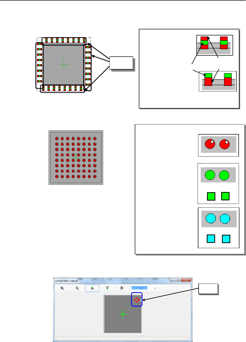
Example of “Component Viewer” screen whose contents vary depending 6.3.3
on the element type
(1) Outer lead/inner lead element
(2) Ball, land, and column elements
Balls, lands, and columns are displayed in different colors respectively.
(3) Mark element
A mark element is indicated as a dotted line circle or rectangle.
◇
Outer lead:
A green spot exists at
the center of the red
rectangle.
◇
Inner lead:
A green spot exists at
the edge of the red
rectangle.
Lead
Green
Red
◇Ball:
Red circle (filled). A
white spot exists in the
upper right part to give a
ball a three-dimensional
appearance.
◇Land:
Lands are indicated as
green circles or
rectangles.
◇Column:
Columns are indicated
as light blue circles or
rectangles.
Mark
or
or
Part 2 Detailed Description of Each Function Chapter 6 General-Purpose Vision Component
6-16
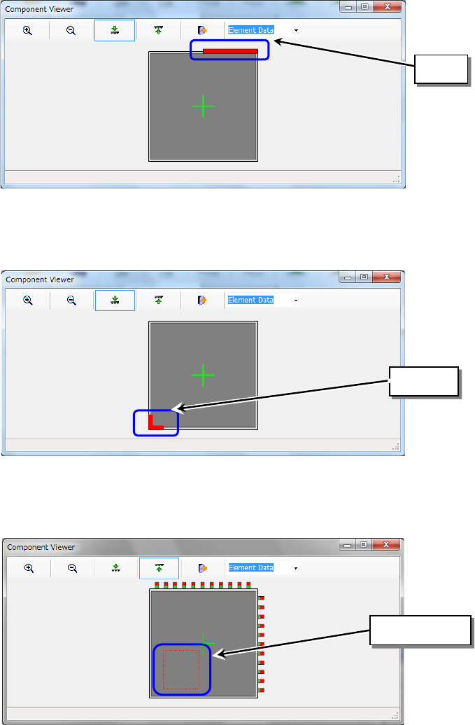
(4) Side element
A side element is indicated as a red line.
(5) Corner element
A corner element is indicated in red.
(6) User definition
A user-defined element is displayed in red.
Side
Corner
User-defined