RS-1_instruction manual.pdf - 第534页
Part 1 B asic O peration Chapter 4 Cr eating a Produc tion Progra m 4- 199 2) Selecting a temp late type Nex t, select “PR” to jud ge a mark. [ ] [ ] [ ] [ ] [ ] [ ] [ ] [ ] [ ] [ ] [ ] [ ] [ ] [ *] PR ******** ** The si…
Part 1 Basic Operation Chapter 4 Creating a Production Program
4-198
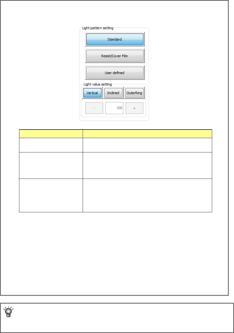
• If the system cannot recognize a mark stably, press the "Light pattern setting" button to set
the light pattern. Be sure to set the light pattern before specifying the top side and left side
of the measurement frame.
When you use the <User defined> button, enter the light value directly.
Select the <Inclined> button, the <Vertical> button or the < OuterRing > button and enter
the desired value into the edit box directly, or change the displayed value with pressing
the <+> button or the <-> button.
* We recommend that you specify a value from 50 to 200 for a user-defined pattern.
If you specify 50 or a smaller value, the amount of light may become unstable.
The [OuterRing] button is displayed only when [Solder Print Misalignment Correction
(option)] is set.
If you want to teach only the inspection frame while holding the same information on a
mark, press the <Next> button. You can skip Step ③.
When the system recognizes a new mark, the <Next> button is disabled.
Light pattern Process
Standard
Select this type if the system recognizes a normal BOC
mark.
Resist/Cover Film Select this type if a mark is not reflected well with the
standard type of light because a resist or cover film is
located over a mark, so the system cannot recognize the
mark stably.
User defined
Select this type if a mark is not reflected with either type of
the light above, and the system cannot recognize a mark
stably.
This selection allows you to set the light amounts of the
vertical, inclined and OuterRing lights directly.
Part 1 Basic Operation Chapter 4 Creating a Production Program
4-199
2) Selecting a template type
Next, select “PR” to judge a mark.
[ ]
[ ]
[ ]
[ ]
[ ]
[ ]
[ ]
[ ]
[ ]
[ ]
[ ]
[ ]
[ ]
[ *]PR
**********
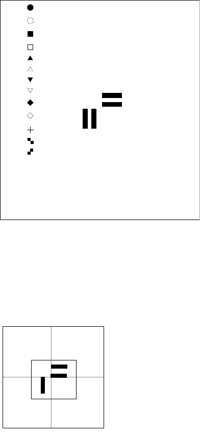
The size of a template is 256 × 256 pixels (approximately a quarter of the screen). If you
specify a too large template, the system displays an error and returns to the procedure for
setting the scale frame.
3) Teaching the center of the template
Press the screen in the up/down direction to
align the * mark with the “PR” position, and
then press the <OK> button.
The message “Select Mark by Up or Down
key” appears on the bottom of the screen.
**********
The scale frame and the crosshair cursor appear on the screen.
Move the crosshair cursor to align it with the center of the template
(th
is position matches the coordinates of a mark specified on the
“PWB” data screen). Press the <OK> button to decide the
center.
The message “TempMatch
– Set Center” appears on the bottom
of the screen.

Part 1 Basic Operation Chapter 4 Creating a Production Program
4-200
4) Teaching the detection frame
When you finish the operation (3), the system automatically displays the window whose size
is 1.5 times that of the frame you set at (1) so that it can be aligned with the center of the
screen (default window).
To change the detection frame, follow the procedure described at (1).
If you do not change the detection frame, press the <OK> button.
When you press the <Prev> button at this point, the system returns to the procedure for teaching
operation of the scale frame.
5) End of teaching
When the system finishes teaching operation for recognizing the template, it displays (*)
next to the mark on the "Program Editor" screen indicate that it finished teaching operation.
Perform the teaching operation for recognizing a mark for all marks to be used.
If you press the <CANCEL> button during teaching, the system finishes teaching at that
point (in this case, the data that has been entered until that point will become invalid).
Even though you press the <CANCEL> button, any device will not move.
• Notes on setting of a template
i) Check to see if there is no pattern similar with the template you set inside the detection
frame.
ii) Set the size of the pattern to 0.5 mm to 3 mm in the same manner as a standard mark.
iii) Specify the designed values (CAD data) as coordinates. The system cannot obtain the
center position correctly when it teaches the user-designated template. Since the system
teaches the pattern by moving the crosshair cursor, the position you specified is regarded
as the center position as it is (Since the system calculates and sets the center position for
the standard mark pattern, any error is not generated).
iv) You cannot execute the [Vision Copy] command for any user-designated template.
Set the detection frame.
Follow the procedure for setting the scale frame.
A
dotted
line indicates the frame for setting a template, but it
is no
t displayed on the screen actually.
The message “Set Left
-Top Point” is displayed on the
bottom of the screen.
When you finish adjusting the frame, press the <OK> button.
The message “Set Right
-Bottom Point” is displayed on the
bottom of the screen.