RS-1_instruction manual.pdf - 第592页
Part 1 B asic O peration Chapter 4 Cr eating a Produc tion Progra m 4- 257 8) <String art> butt on ([F7] k ey) This button d i splay s the sting art bas ed on the result of t he “ SWE EP ” oper atio n performed dur…
Part 1 Basic Operation Chapter 4 Creating a Production Program
4-256
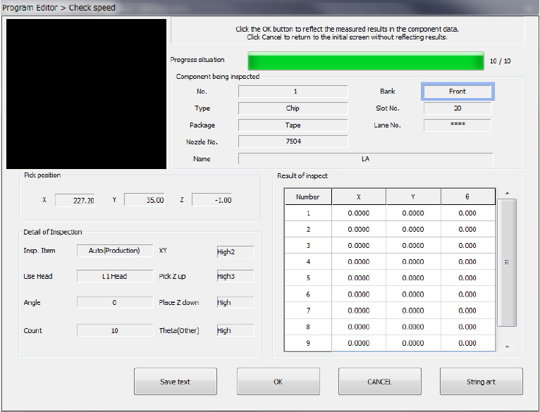
When the system finishes the inspection, the following result screen appears on the screen.
1) Component being inspected
Data on a component and its pick-up position appear here.
2) Pick position
The coordinates of a component pick-up position appear here.
3) Detail of Inspection
Data on the speed check the system has done appears on the screen.
4) Result of inspect
The result values obtained with the speed check appear here. An error of each axis, X, Y
and θ is displayed.
When you select “Pick Z up,” whether a component was picked up successfully or not is
displayed.
5) <Save text> button
This button saves the inspection result as a text.
6) <OK> button
This button validates the inspection result, and stores the obtained values in the Component
data. Then, the “Check speed” dialog box reappears on the screen.
(The data to be updated is the speed of the axis displayed in the “Detail of Inspection”
column.)
7) <CANCEL> button
This button cancels the inspection result, and displays the “Check speed” dialog box again.
Part 1 Basic Operation Chapter 4 Creating a Production Program
4-257
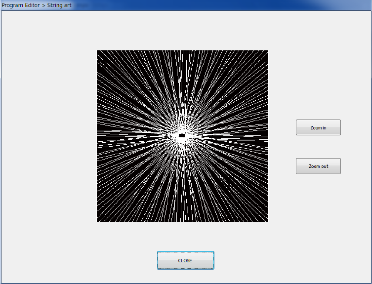
8) <String art> button ([F7] key)
This button displays the sting art based on the result of the “SWEEP” operation performed
during measurement.
9) <Prev. component> button and <Next component> button
These buttons are displayed when there is any alternative component for the currently
displayed component.
10) <Exit> button
The inspection is terminated and the previous screen reappears.
Part 1 Basic Operation Chapter 4 Creating a Production Program
4-258
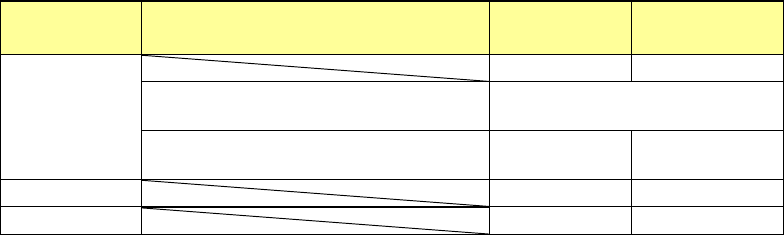
(2) Each operation to be done when the system is checking the speed
1) Returning a component after the check
After checking the speed, the system returns a component to its original position or discards
it. Which operation is to be done varies depending on the packaging style as shown in the
table below. The system discards a component to a place specified with the setting of the
“Compo reject to” field of the Component data screen. If you select “Protect” in this field,
the system discards a component according to this setting. Since a component whose size
is 1 mm or less may stand on its side or may be turned over when it is returned, the system
displays the question dialog box that allows you to select how to handle the component.
Packaging
style
Condition 2
Returning a
component
Discarding a
component
Tepe
―
○
The shorter side length of the outer
dimensions is 1 mm or less.
Query * 1
The shorter side length of the outer
dimensions is 1 mm or more.
○ ○ *2
Tray
○
○
*2
Stick
―
○
*1 The system displays the message to ask you whether to return or discard a component.
*2 When you select the “IC collection belt” or “Protect” for the menu item “Component reject
to,” the system operates according to the corresponding setting.
2) Selecting a feeder from which the system picks up a component
If two or more feeders are specified for the same component type (in Pick data), the system
starts picking up a component based on the data entered first. You can change the feeder
to be used intentionally also.
3) Manual pick-up of a component
If there is no Pick data created, you can attach a component onto a nozzle manually also.
In such a case, you cannot enter any pick-up coordinates. You cannot operate a feeder
either.
If you attach a component to the nozzle manually, the system cannot discard it if the length
of the shorter side of its outer dimensions exceeds 33.5 mm. Therefore, the system moves
the component to the protection position after measuring it.