RS-1_instruction manual.pdf - 第394页
Part 1 B asic O peration Chapter 4 Cr eating a Produc tion Progra m 4- 59 (3) C enter ing 1) Laser centering Set the menu items “ Nozz l e No., ” “ V acuum level, ” “ Laser he ight, ” “ Com p Shape ” and “ Gripper no zzl…

Part 1 Basic Operation Chapter 4 Creating a Production Program
4-58
⑨ MTC
- MTC speed : You can specify the operation speed of the shuttle.
When you decrease this speed, the MTC can supply the main unit with
components more stably, but the cycle time becomes longer.
- Pickup : You can specify the type (Large or Small) of the pad on the MTC pick-up
side.
* When you select “Auto,” the system selects both pads for the same type
components during production as long as the size of these components is
in the range of □10 mm to □14 mm (□10 mm to □16 mm when a
seesaw nozzle is used), and then picks up these components.
- Shuttle : You can specify the type (Large, Small or Mecha) of the pad on the MTC
shuttle side.
* Since a ball component such as a BGA component cannot be picked up
with the pad of the MTC shuttle (that is, vacuum cannot be used),
specify “Mecha” (for clamping the outside of a component).
* When “Tray return” is specified for the menu item “Component reject to”
on the “Add info” tab, the choice “Mecha” cannot be selected.
◆ Initial values for the MTC pads
Menu item displayed on
the screen
Default value
Pickup
–
When the length of the shorter side, width or length, of
the component dimensions is
Less than 16 mm : Small
16 mm or more : Large
Shuttle
–
When the component type is BGA: Mecha
– When the component type is not BGA and the length
of the shorter side, width or length, of the component
dimensions is
Less than 16 mm : Small
16 mm or more : Large
- MTC auto teaching : When you check off this check box, the system automatically
calculates the center of a component at each point to show you
the center of the component with the spot light. During
production, auto teaching is performed when a component is
pulled out for the first time after the number of components is
changed once auto teaching is performed.
⑩ MTS
• MTS speed
Specify the tray pull-out speed. This prevents lightweight components from jumping.
• MTS mark recognition
Then the MTC is used, and the pick reference position mark recognition is set to "Do,"
the pick reference position mark is recognized when the tray where the set components
are placed is pulled out, and the execution coordinates such as the pick and the
component return is corrected.
It takes the recognition time though the pick accuracy improves when "Do" is selected.
⑪ DTS
- DTS speed: Specify the speed at which a tray is pulled out. This setting is provided to
prevent a lightweight component from bouncing.
Part 1 Basic Operation Chapter 4 Creating a Production Program
4-59
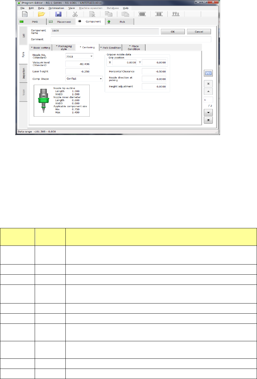
(3) Centering
1) Laser centering
Set the menu items “Nozzle No.,” “Vacuum level,” “Laser height,” “Comp Shape” and
“Gripper nozzle data.”
① Nozzle No.
Select the number of the nozzle that can pick up a component stably from the pull-down list.
The standard nozzle numbers (7500 to 7509) and other nozzle numbers assigned by setup
are displayed.
② Vacuum level
During PWB production, whether a component was picked up normally is determined
according to the vacuum level to be applied when there is no component (set with the
“Machine setup” application) and this “Vacuum level” after pick-up operation. Enter the
vacuum pressure applied when a component is picked up with the nozzle whose number is
specified with the “Nozzle No.” Touch the displayed vacuum level, and enter the value.
Vacuum
pressure
Nozzle
No.
Applicable component type
-82.436 7500
1005, 1608, SOT (mold part 1.6 x 0.8),
2012, SOT (mold part 2.0 x 1.25)
-82.436 7501 0603
-82.436 7502 1005
-82.436 7503
1608, SOT (mold part 1.6 x 0.8),
2012, SOT (mold part 2.0 x 1.25)
-82.436 7504 2012, 3216, SOT (mold part 2.0 x 1.25), SOT23
-82.436 7505 Aluminum electrolytic capacitor (small), tantalum capacitor, trimmer
-82.436 7506
Aluminum electrolytic capacitor (medium),SOP (narrow width), HSOP
(narrow width), SOJ, connector
-82.436 7507
Aluminum electrolytic capacitor (large),SOP (wide width), HSOP (wide
width), TSOP, QFP, PLCC, SOJ, connector
-82.436 7508 QFP, PLCC
-82.436 7509 0402
The vacuum level displayed at first is a value for your reference. Since the finish of the surface of
a component varies depending on its manufacturer, operate the machine to measure the
component to use it.
Part 1 Basic Operation Chapter 4 Creating a Production Program
4-60
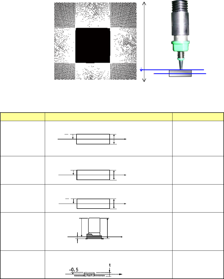
③ Laser height
Set the measurement height attained when the system centers a component with laser.
Enter the distance from the nozzle tip to the measurement position to which the laser beam
is irradiated.
The initial value is automatically determined by the component height and the component
type. However, some components may require alteration of the initial value. If such portions
that do not intercept laser rays completely as the end of lead and the top surface/bottom
surface of component are at the laser plane (laser height), a laser recognition error may
occur. Select a height that assures stable recognition (for example, if the position measured
with laser is cylindrical-shaped or transparent-colored).
♦ Default Laser height
Default laser heights are set for some component types and heights.
Table shows the relation between component heights and default laser heights.
Component type Measurement position Laser height (mm)
Square chip
t
- -
2
Square chip
(LED)
- (t –0.15)
MELF
t
- -
2
Aluminum
electrolytic
capacitor
- (t –β)
β= 0.35
GaAsFET
-0.5
2
t
-
部品高さ t
レーザ測定位置
部品高さ t
レーザ測定位置
- (t - 0.15)
2
t
-
部品高さ t
レーザ測定位置
部品高さ t
レーザ測定位置
- ( t -β)
β
Component height
Measurement position
with laser
Component height
Measurement
position with laser
Measurement
position with laser
Component height
Component height
Measurement
position with laser
Measurement position
with laser
Component height
-Z
0
Nozzle tip
Laser height