RS-1_instruction manual.pdf - 第411页
Part 1 B asic O peration Chapter 4 Cr eating a Produc tion Progra m 4- 76 4) Speed When a smal l nozzle is u sed to pic k up compon ents or when a vac uum leak age occurs f rom a groove on the t op surface of the compon …
Part 1 Basic Operation Chapter 4 Creating a Production Program
4-75
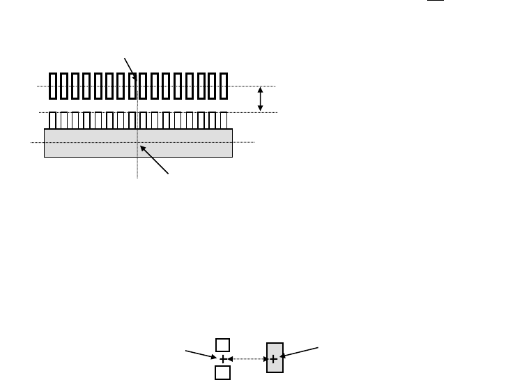
Example 3: To place a component as shown below, enter "X = 0, Y = +3" into the "Place
Offset" field.
Note 2: Enter the offset value with regarding the placement angle as "0".
Example 4: If the placement angle of a component is "90," enter the "Place Offset" field by
assuming the placement angle to be "0." In the case shown below (placement
angle of "90"), enter "X = 0, Y = 2."
Note 3: To enter an offset value, we have two methods: One is to enter the offset value into
the "Place Offset" field on the "Component" screen and the other is to add or subtract
the offset value to or from "X" and "Y" fields on the "Placement" screen.
For entry of placement data, however, an offset value must be adjusted one by one for
each placement position. Therefore, in the case of placing components of the same
type on a number of positions, or if you do not want to change the placement data,
then enter the offset value in the "Place Offset" field on the "Component" screen.
Note 4: If you change a value in the “Laser position” field of some components on the
“Centering” tab of the “Component” data screen, the center position of the component
centered with laser may be changed. Therefore, you may be able to adjust the
component placement position by changing the value in the “Laser position” field
without entering any value in the “Place Offset” field. However, in this case, you
have to set the “Laser position” field so that the system can center a component
stably.
Center position of a component
centered with laser
Coordinates points of the component placement position
3
2
Coordinates of the component
placement position
Center position of a component
centered with laser

Part 1 Basic Operation Chapter 4 Creating a Production Program
4-76
4) Speed
When a small nozzle is used to pick up components or when a vacuum leakage occurs from
a groove on the top surface of the component, the acceleration of the XYZ axis can be
changed from the default value.
- XY
From the drop-down list, select the speed that the XY-axes accelerate until they move to
the component placement position after they pick up a component (in 10 steps).
- Place Z down
From the drop-down list, select the speed that the Z-axis accelerates (to adjust the stress
imposed on a component) when it moves down at the component placement position.
- Place Z up
From the drop-down list, select the speed that the Z-axis accelerates (to adjust the stress
imposed on a component) when it moves up at the component placement position.
① Laser centering
- Theta (Measure)
Specify the theta rotation speed from the drop-down list.
This value sets the speed that the theta axis accelerates when a component is
recognized with laser.
This value is effective for all rotating operations except a rotation for measurement of a
component with laser when a head holds a component.
- Theta (Other)
Specify the theta rotation speed by the drop-down list.
This speed is effective for all rotation operations except for a rotation for measurement
operation with laser when a head holds a component.
This value sets the speed that the theta axis accelerates when a component is not
recognized with laser.
② Vision centering
- Theta speed
Specify the theta rotation speed from the drop-down list.
This value is effective for all rotating operations except a rotation for measurement of a
component with laser when a head holds a component.
5) Trial
In the same manner as the setting on the “Placement” data screen, on the “Production”
(Trial mode) screen the system places only components for which the “Trial” field is set to
“Yes.”
When you select the <Yes> button in the “Trial” field on this “Component” data screen, the
system sets all placement positions of a component by one operation.
If you want to specify whether to perform a trial operation on each component placement
position, use the “Placement” data screen.
6) Release check
This check is intended for laser centering components. This function checks whether any
component is attached to the nozzle after completion of a placing operation.
It takes some time for the system to check that a component is released (since the
system checks it while it is put in the pause state). Normally select the <No> button.
Part 1 Basic Operation Chapter 4 Creating a Production Program
4-77
7) Component skip
When you select the <Yes> button for this “Component skip” field, the system skips the
corresponding component during production and does not place it on a board.
The placement data record for a component specified to be skipped on the database is not
used for PWB production, but it is not listed on the “Not placed” list.
When you load the component information from the database, the <No> button is
selected for this “Component skip.”
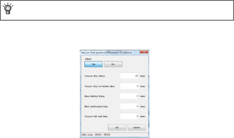
8) Vacuum time adjustment
Specify whether to adjust the vacuum time or not.
When you press the <Setting> button, the following screen appears.
When you select the <Yes> button for the menu item “Adjust,” you can enter an adjustment
value for each item of “Vacuum stop timing,” “Vacuum stop correction value,” “Blow starting
timing,” “Blow continuing timing” and “Vacuum OFF wait time” in milliseconds.
9) Control
Specify how to control the stroke to be applied to placement of a component.
When a nozzle for controlling low load is selected on the “Centering” tab, the <Low load>
button and the <Load graph> button are enabled on the screen.
When you select the <Low load> button for this menu item, the input unit for the menu item
“Placing stroke” is changed to [g], and the setting of the “Place Z down” field of the menu
item “Speed” is changed to “FC speed.”
When you press the <Load graph> button, you can check the pressure that can be applied
with the nozzle.