RS-1_instruction manual.pdf - 第903页
Part 2 D etaile d Descript ion of E ach Functi on Chapter 12 Handling th e Optional Device s 12 - 19 12.3.3.2 Checking the height Set a tray base on the f i rst stage of the MTS. A fter return - to - origin operation, di…
Part 2 Detailed Description of Each Function Chapter 12 Handling the Optional Devices
12-18
3) Push the main unit stopper against the feeder bank.
Part 2 Detailed Description of Each Function Chapter 12 Handling the Optional Devices
12-19
12.3.3.2 Checking the height
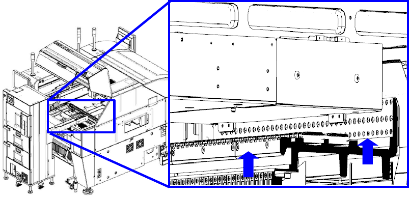
Set a tray base on the first stage of the MTS. After return-to-origin operation, display the “MTS
position offset” screen from the “Position setting” screen invoked from the “Machine Setup” screen,
and then press the <Meas.> button. The system pulls out the tray base, and automatically
measures the height. Check the screen shown below, and repeat this measurement operation and
adjustment of the height until a value in the range of – 10.00 mm to – 9.00 mm is displayed in each
of the “Measurement 1” field, the “Measurement 2” field and the “Measurement 3” field.
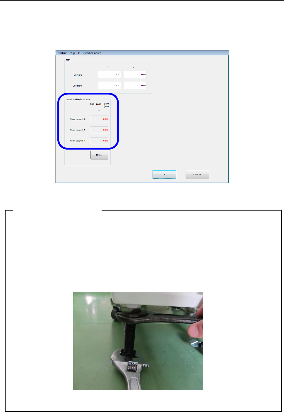
After the adjustment has been completed, tighten the adjuster nuts to secure the height.
• As the adjuster is turned one rotation, the height changes 2.5 mm.
• Since the adjuster screw has a play, pay special attention to the following points when
securing the adjuster with the nut.
① Adjust the Z-height to around -9.15 mm by taking the play into consideration.
② When tightening the fixing nut, put a spanner on the height adjustment nut and
hold it so that the adjuster does not turn.
• Turn four casters and four adjusters evenly to install them.
• After the setup has been completed, insert the RF08AS into the rear lane No. 14.
When there is no interference, this position becomes the correct position.
Tips on leveling work
Part 2 Detailed Description of Each Function Chapter 12 Handling the Optional Devices
12-20
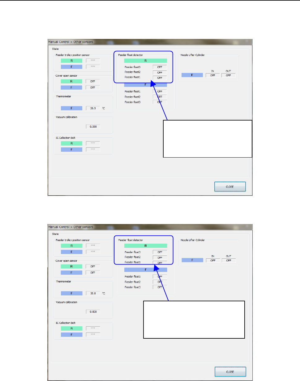
12.3.4 Checking the Sensor (When a TR8SR is selected)
Select Manual Control>Others>Other sensors and perform the following work using the RF08AS to
check the operation status of the rear feeder float sensor.
• Open the feeder cover intentionally to check that the sensor turns ON when the feeder is
inserted into the bank.
• When pulling out the feeder from the bank with the feeder cover closed correctly, check that
the feeder can be pulled out with the sensor turned OFF.
If incorrect detection or non-detection occurs, readjust the height of the feeder float sensor on the
TR8SR side.
The feeder float detector is
• ON when detected.
• OFF when not detected.
The feeder float detector 2
・
3 is
• ON when detected.
• OFF when not detected.