RS-1_instruction manual.pdf - 第604页
Part 1 B asic O peration Chapter 4 Cr eating a Produc tion Progra m 4- 269 (3) Operating metho d for each t eaching pro cessing ① C ompon ent measurement When you se lect "Comp onent height" or "P i ck vac…
Part 1 Basic Operation Chapter 4 Creating a Production Program
4-268
How to return a component varies depending on the packaging style of a component.
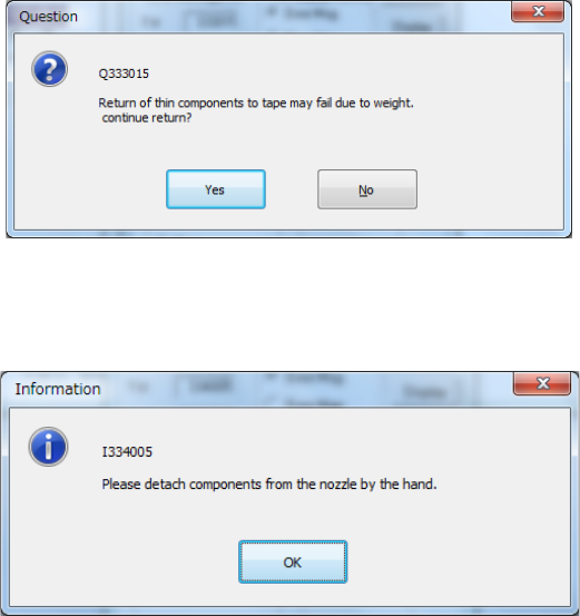
When the size of a component is 1 mm or less, the system displays the message that allows
you to select whether to return it or discard it after measuring it.
When a component is returned manually, the following message appears on the screen.
Remove the component from the nozzle manually
Part 1 Basic Operation Chapter 4 Creating a Production Program
4-269
(3) Operating method for each teaching processing
① Component measurement
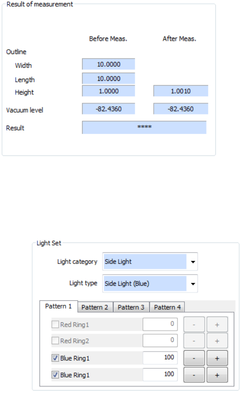
When you select "Component height" or "Pick vacuum pressure" in the measurement items
on the setting dialog box, component measurement is executed. When you press the
<Next> button in the "Start" status, component measurement is performed. After
completion of the measurement, values are displayed in the “After Meas.” field of the “Result
of measurement” column.
② Light Set
Set the VCS lighting type to be used for component measurement and adjust the brightness.
After component measurement is performed or when component measurement is not
performed, it is executed after a start. Adjust the brightness so that the pole, lead, and
outline of a component can be recognized.
a) Select the VCS light type in the “Light category” list box and the “Light type” list box.
b) Specify whether to use each light unit or not and its brightness (20 to 200).
c) The values of Pattern 1 to Pattern 4 can be saved. Select a pattern to be used by the
corresponding tab.
d) After completion of lighting setting, press the <Next> button to proceed to inclination
teaching.
Part 1 Basic Operation Chapter 4 Creating a Production Program
4-270
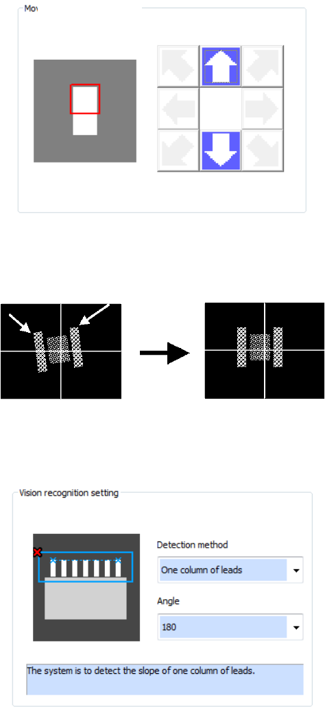
③ Inclination teaching
Teaching to correct the inclination of the component is executed.
a) Pattern movement (for division recognition)
The pattern is moved to the pattern position where a component portion to be used for
inclination correction is displayed. Unless division recognition is not performed, pattern
movement is not required because the whole component can be displayed.
b) Specifying the upper left/upper right pole position (for pole/land setting)
The upper left and upper right poles of the component are detected and the inclination of the
2 poles is corrected.
c) Vision recognition setting (for lead/outline setting)
Auto detection of a component portion is performed and the inclination is corrected. At this
time, set the detecting method and detecting angle.
Pattern movement