RS-1_instruction manual.pdf - 第739页
Part 2 D etaile d Descript ion of E ach Functi on Chapter 8 Machine Set up 8- 31 IC collecti on belt pos ition When you se lect [IC co llection b elt position] , the following screen a ppears. ( 1) Se tting items No. Ite…
Part 2 Detailed Description of Each Function Chapter 8 Machine Setup
8-30
8.3.4 Position setting
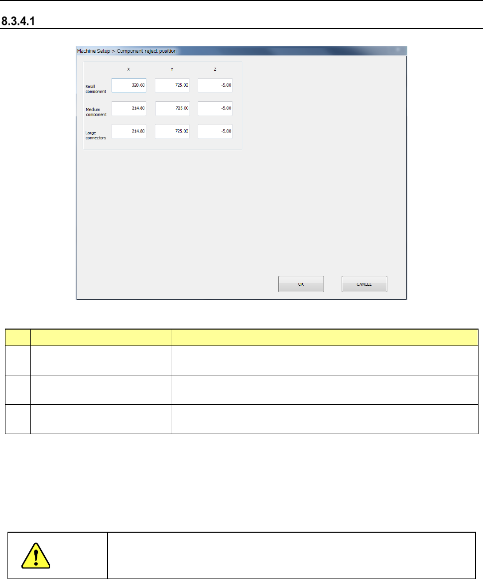
Component reject position
When you select [Component reject position], the following screen appears.
(1) Setting items
No.
Item
Description
1 Small component (X, Y, Z)
Discard position of a small size component
(long side of 15 mm or less)
2 Medium component (X, Y, Z)
Scrapping position
for medium components (components with a long
side of 180 mm or less and a short side of 35.5 or less)
3 Large component (X, Y, Z)
Scrapping position for large components (components with a long
side of 180 mm or less a short side of 50 mm or less)
(2) How to set
1) Enter a value each in the edit box for each of X, Y, and Z.
2) Press the <Teaching> button to enter values. Regardless of which field the input focus
is located in, “X” or “Y,” values are entered in both fields at the same time.
3) To t each the “Z” coordinate, the input focus should be located in the “Z” field.
CAUTION
To avoid a risk of injury, do not place your hand in the machine, nor move your
face or head close to the machine while the machine is teaching data.
Part 2 Detailed Description of Each Function Chapter 8 Machine Setup
8-31
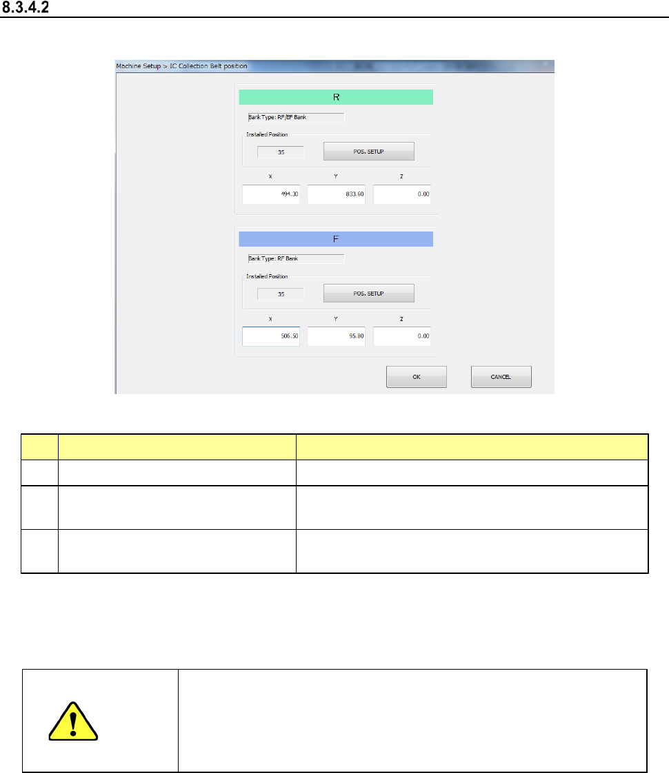
IC collection belt position
When you select [IC collection belt position], the following screen appears.
(1) Setting items
No.
Item
Description
1 Bank type Bank at which IC collection belt is attached
2
IC Collection Belt Installed Position
(Front/Rear, feeder hole number)
Position at which the IC collection belt is attached
3
IC Collection Belt component
discarding position (X, Y, Z)
Position of the IC collection belt at which a component
is discarded
Set each item by teaching or software keyboard.
When the input focus is located in the “X” or “Y” field, values for the X and Y coordinates are
taught. When the input focus is located in the “Z,” a value for the Z coordinate is taught
CAUTION
- To prevent an accident causing an injury, never put your hand in the
machine or bring your face or head close to the machine while it is
teaching data.
- If you optimize a production program without setting the IC collection
belt position, a feeder may be overlapped with the IC collection belt.
Part 2 Detailed Description of Each Function Chapter 8 Machine Setup
8-32
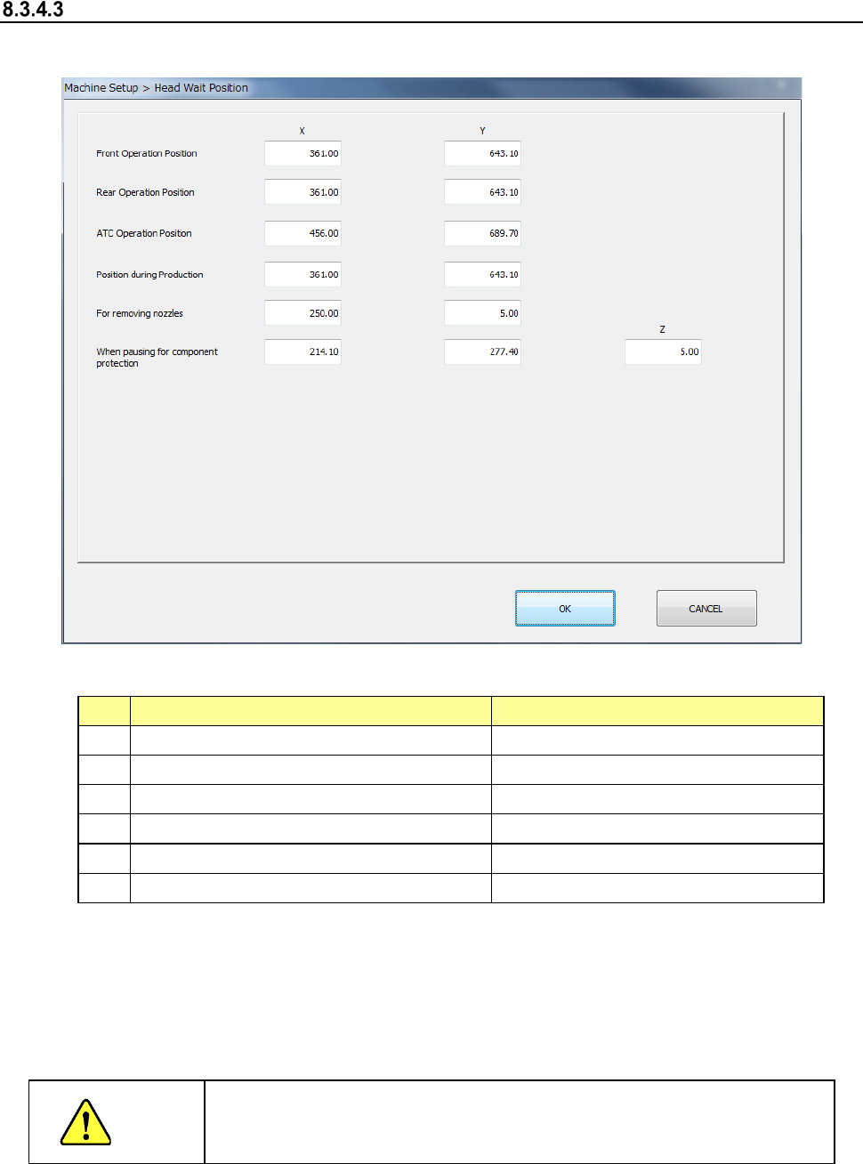
Head Wait Position
After you select [Head wait position], the following screen appears.
1) Setting items
No.
Item
Description
1
Position for front-side operation
X and Y positions
2 Position for rear-side operation X and Y positions
3
ATC Operation Position
X and Y positions
4 Position for production X and Y positions
5
When removing nozzles
X, Y positioning
6
When pausing to protect components
X, Y and Z positions
2) How to set
1) Enter each value in the text box for each of X, Y and Z.
2) Enter each data by teaching. In this case, regardless of which field the input focus is
located in, “X” or “Y,” coordinates are entered in both fields at the same time.
3) To teach the Z coordinate, the input focus should be located in the “Z” field.
CAUTION
To avoid a risk of injury, do not place your hand in the machine, nor
move your face or head close to the machine during while the machine
is teaching data.