RS-1_instruction manual.pdf - 第756页
Part 2 D etaile d Descript ion of E ach Functi on Chapter 8 Machine Set up 8- 48 Bad mark teaching When you se lect [Bad m ark teac hing], t he following sc reen appe ars. ( 1) Se tting items No. It em Descripti on 1 Pos…
Part 2 Detailed Description of Each Function Chapter 8 Machine Setup
8-47
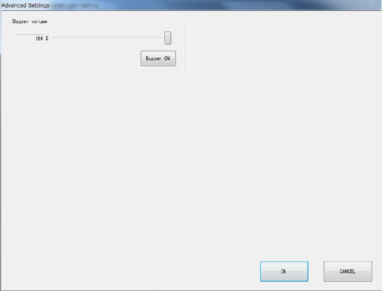
8.3.6.1.1 Advanced Settings
When you click <Advanced Settings> on the Signal Light Setting screen, the screen shown below
will appear.
(1) Buzzer volume
You can set the buzzer sounding volume by moving the slider.
When you click the <Buzzer ON> button, the buzzer sounds using the set volume. Clicking
this button again will stop the buzzer sound.
Part 2 Detailed Description of Each Function Chapter 8 Machine Setup
8-48
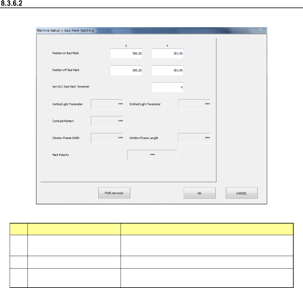
Bad mark teaching
When you select [Bad mark teaching], the following screen appears.
(1) Setting items
No. Item Description
1
Position with a mark
X-coordinates/Y-
coordinates of the center position of the bad
mark
2
Position without any mark
Position without any bad mark (top surface of the board)
3
OCC bad mark threshold value
setting
Threshold value when recognizing a bad mark by camera
(2) How to set
1) Enter each value from the software keyboard
2) Enter each value by using the “Teaching” function displayed in the Operation area.
3) For XY position, values are fetched and incorporated simultaneously regardless of the
input focus position.
4) Put a focus onto the OCC bad mark threshold value setting and execute teaching by
pressing “Teaching” of the operation area.
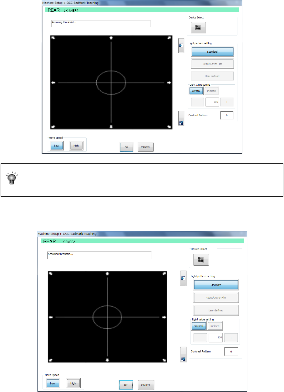
(3) Executing operation (OCC)
1) Put a focus onto the OCC bad mark threshold value setting and execute teaching by
pressing “Teaching” of the operation area.
Part 2 Detailed Description of Each Function Chapter 8 Machine Setup
8-49
2) After checking the coordinates of the bad mark position, specify the measurement
frames (upper left and lower right). Change the size of the measurement frame by the
direction key on the teaching screen and then press the <ENTER> button to set it
definitively.
If the mark is imaged in black for the board, press the camera button for device
selection. The polarity is changed and the black-imaged mark for the board
becomes white. A changeover of the polarity by camera button is enabled only
when the scale frame is entered.
3) After setting the measurement frame definitively, a threshold value measuring operation
is performed.
The position with a mark and the position without any mark are alternatively recognized.