RS-1_instruction manual.pdf - 第164页
Part 1 B asic O peration Chapter 2 Pr oduction 2- 53 No. Menu item Description 1 PWB productio n Number of PWB s produced Number of PWB s already prod uced after the prod uction management informati on was clear ed the l…
Part 1 Basic Operation Chapter 2 Production
2-52
2.9 Production Management Information (Window)
When you select “PWB production” as the production mode, the production management
information is saved. This section describes the production management information saved during
production.
Production management information
(1) Conditions under which the production management information is collected
① When “PWB production” is selected as the production mode, and components are placed on
all component placement positions of a board
② Once the information is collected, new information collected during the next production is
added to the previous production management information.
If you want to collect new data only, clear the information already stored.
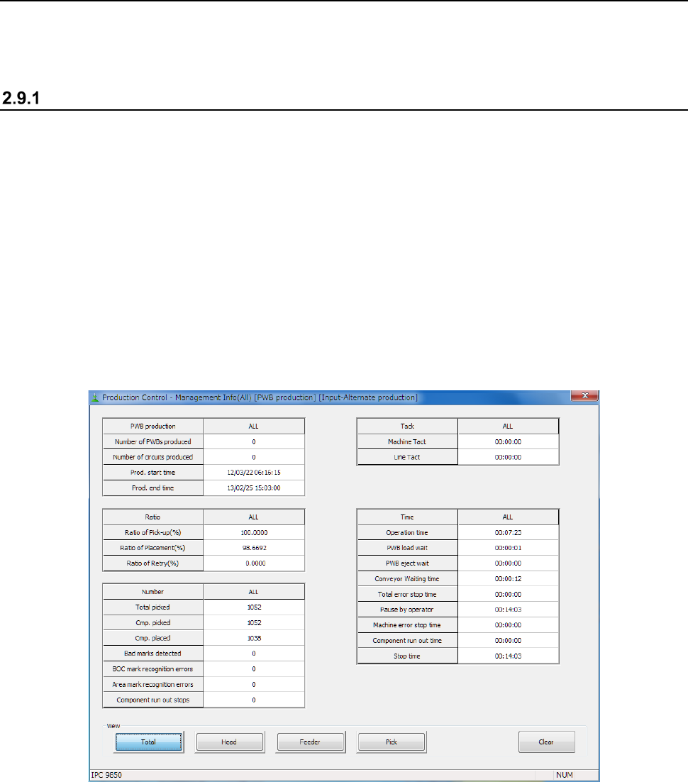
(2) Production management information screen
Click the [Window] command from the “Product” menu, and select the production management
information to be displayed on the screen.
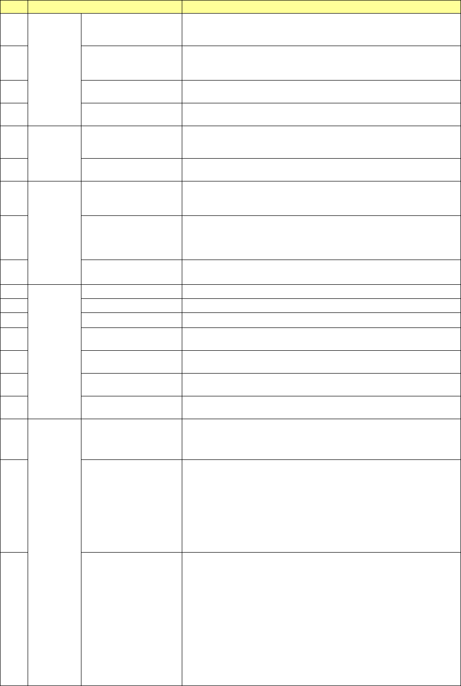
(3) Contents
1) Production management information (All)
Part 1 Basic Operation Chapter 2 Production
2-53
No.
Menu item
Description
1
PWB
production
Number of PWBs
produced
Number of PWBs already produced after the production management
information was cleared the last time (number of PWBs produced
completely only)
2
Number of circuits
produced
Number of circuits already produced
(Number of PWBs produced × Number of circuits – Number of bad
marks detected)
3
Prod. start time
Date and time the machine started PWB production for the first time
after clearing the production management information last time.
4
Prod. end time
Date and time the machine finished PWB production with this
production program last time.
5
Tac t
Machine Tact
Shows the time from when one board is loaded into the machine until
when the board is ejected..
The cycle time per station is displayed also.
6 Line Tact
Shows the time from when one board is ejected until when the next
board is ejected.
7
Ratio
Ratio of Pick-up (%)
Shows the successful component pick-up ratio.
(Number of successful component pick-ups / (Number of successful
component pick-ups + Number of component pick-up errors) )× 100
8 Ratio of Placement (%)
Shows the successful component placement ratio.
(Number of successful component placements / (Number of
successful component placements + Number of component
placement errors)) × 100
9 Ratio of Retry (%)
Shows how frequently a component pick-up retry has occurred.
(100 – “Ration of Pick-up”)
10
Number
Total picked Total number of picked-up components
11
Cmp. picked
Total number of components picked up successfully
12 Cmp. placed Total number of components placed successfully
13 Bad marks detected
The total number of circuits for which bad mark is detected and
detected area bad marks.
14
BOC mark recognition
errors
Number of BOC mark recognition errors that have occurred
15
Area mark recognition
errors
Number area mark recognition errors that have occurred
16
Component run out
stops
How many times the machine stopped due to a component run-out
error
17
Time
Operation time
Accumulated time from when PWB production started until when it
finished excluding stop time and waiting time for a board (pause is not
included in this time period)
18 PWB load wait
Shows the accumulated time that passed until the In sensor was set
to ON.
Note that if there is any board on the Out buffer when the clamped
board is released, the time is counted as the “PWB eject wait” time.
In addition, if there is no board on the Out buffer when the clamped
board is released and the In sensor or the Wait sensor is already set
to ON, the time is not added to the “PWB load wait” time. Any time
period when the machine paused while the machine was waiting for a
board to be loaded into it is not included in this “PWB load wait” time.
19 PWB eject wait
Shows the accumulated time that passed from when the clamped
board was released till when the Out sensor was set to OFF (until
when a board was ejected if there was the board on the Out buffer) if
the Out sensor was set to ON (when there was a board on the Out
buffer) when the clamped board was released.
Note that if there is no board on the Out buffer when the clamped
board is released, the time is not added to the “PWB eject wait” time.
However, if a board is the last one, the time passes from when the
clamped board is released till when the last board finishes being
transported is added to the “PWB eject wait” time regardless of the
state of the Out sensor, ON or OFF. In addition, any time period
when the machine paused while the machine was waiting for a board
to be ejected from it is not included in this “PWB eject wait” time.
Part 1 Basic Operation Chapter 2 Production
2-54
No.
Menu item
Description
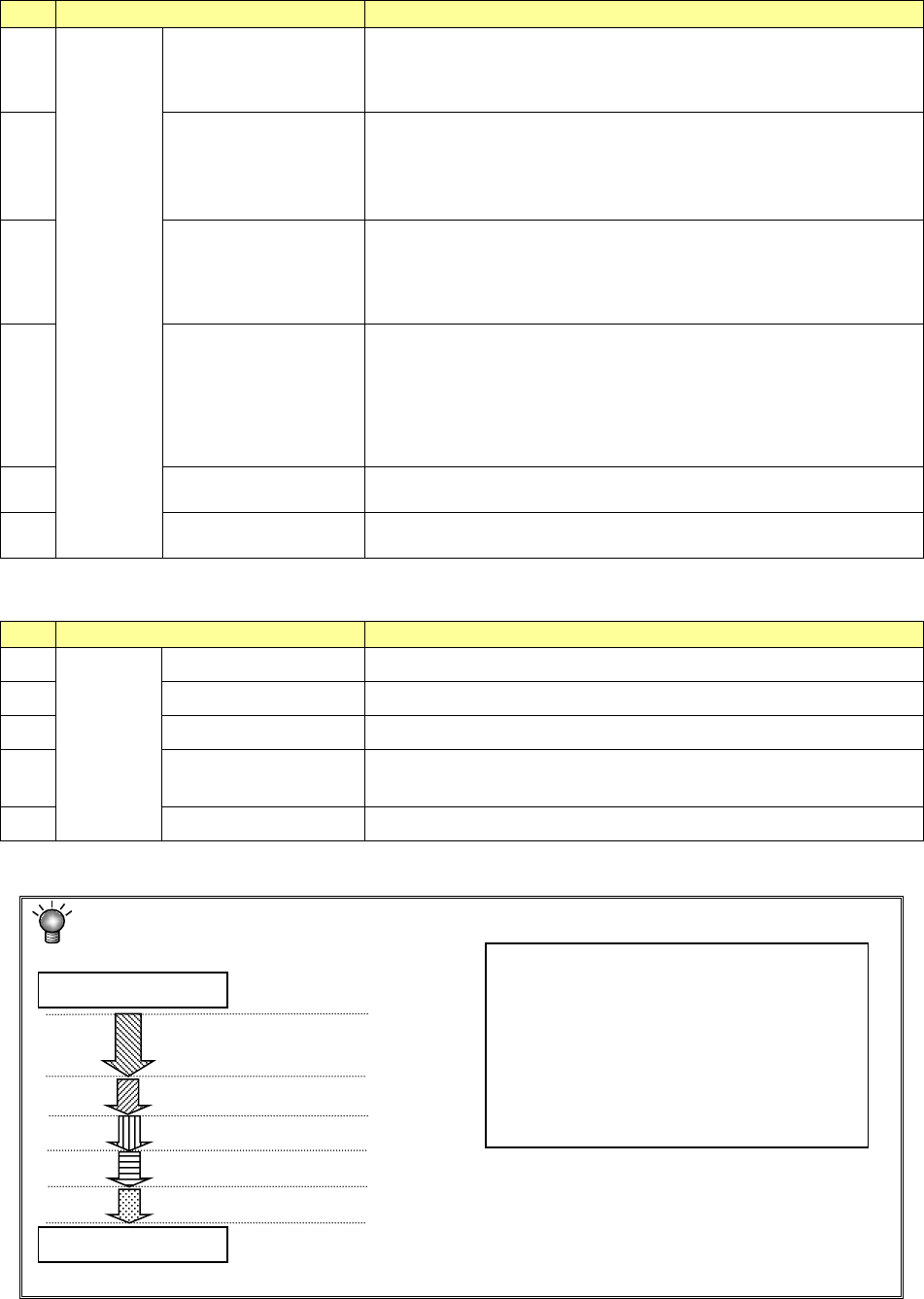
20
Time
Conveyor Waiting
time
Accumulated time from when a board starts being transported until
when finishes being transported.
Note that the time period when the machine pauses temporarily while
it is transporting a board is not included in this time period.
21 Total error stop time
Accumulated time periods when the machine could not produce any
PWB due to an error including pause period and the Emergency Stop
time from start of PWB production to end of it
“Total error stop time” = “Machine error stop time” + “Component run
out time”
22 Pause by operator
Accumulated time periods when the machine stopped according to
the user request (by pressing the <STOP> switch)
Pause for protecting a component and cycle stop are regarded as a
result of the user request, and added to this “Pause by operator” time
period.
23
Machine error stop time
Accumulated pause time: pause caused when the menu item “Stop
system on any error” is checked on the “Operation option” menu,
pause caused because the machine cannot continue the current PWB
production (the IC recovery belt is full of components) and an
asynchronous event (the bank is moved down). Note that if the
machine pauses because components run out, it is added to the
“Component run out time” below.
24
Component run out
time
Accumulated time periods when the machine paused because
components run out or due to the Retry list
25
Stop time
Total time of the “Pause by operator,” “Machine error stop time” and
“Component run out time.”
“View” allows you to change the displayed management information.
No.
Menu item
Description
1
View
Tot al Shows the total management information.
2 Head Shows the production management information per head.
3 Feeder Shows the production management information per feeder.
4
Pick Sorts the component pick-up rates at each component supplied
position and shows them.
5 Clear Clears the production management information.
Each process of production is defined as follows:
A Production
(including board transport time)
Start of production
End of production
B Pause button ON
C Emergency stop button ON
D An error (such as a recognition error) occurs.
E Components run out occurs.
•
Operation time → A
•
Total error stop time → C + D + E
•
Pause by operator → B
•
Machine error stop time → C + D
•
Component run out time → E
•
Stop time → B + C + D + E