RS-1_instruction manual.pdf - 第166页
Part 1 B asic O peration Chapter 2 Pr oduction 2- 55 2) Manageme nt Info (Head) The product i on manag ement informati on per head is displa yed. “V iew” allows yo u to change the displaye d management inform ation. No. …
Part 1 Basic Operation Chapter 2 Production
2-54
No.
Menu item
Description
20
Time
Conveyor Waiting
time
Accumulated time from when a board starts being transported until
when finishes being transported.
Note that the time period when the machine pauses temporarily while
it is transporting a board is not included in this time period.
21 Total error stop time
Accumulated time periods when the machine could not produce any
PWB due to an error including pause period and the Emergency Stop
time from start of PWB production to end of it
“Total error stop time” = “Machine error stop time” + “Component run
out time”
22 Pause by operator
Accumulated time periods when the machine stopped according to
the user request (by pressing the <STOP> switch)
Pause for protecting a component and cycle stop are regarded as a
result of the user request, and added to this “Pause by operator” time
period.
23
Machine error stop time
Accumulated pause time: pause caused when the menu item “Stop
system on any error” is checked on the “Operation option” menu,
pause caused because the machine cannot continue the current PWB
production (the IC recovery belt is full of components) and an
asynchronous event (the bank is moved down). Note that if the
machine pauses because components run out, it is added to the
“Component run out time” below.
24
Component run out
time
Accumulated time periods when the machine paused because
components run out or due to the Retry list
25
Stop time
Total time of the “Pause by operator,” “Machine error stop time” and
“Component run out time.”
“View” allows you to change the displayed management information.
No.
Menu item
Description
1
View
Tot al Shows the total management information.
2 Head Shows the production management information per head.
3 Feeder Shows the production management information per feeder.
4
Pick Sorts the component pick-up rates at each component supplied
position and shows them.
5 Clear Clears the production management information.
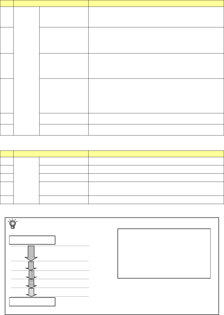
Each process of production is defined as follows:
A Production
(including board transport time)
Start of production
End of production
B Pause button ON
C Emergency stop button ON
D An error (such as a recognition error) occurs.
E Components run out occurs.
•
Operation time → A
•
Total error stop time → C + D + E
•
Pause by operator → B
•
Machine error stop time → C + D
•
Component run out time → E
•
Stop time → B + C + D + E
Part 1 Basic Operation Chapter 2 Production
2-55
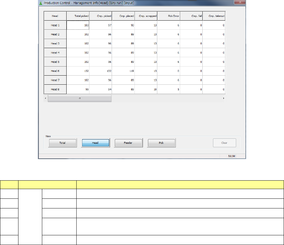
2) Management Info (Head)
The production management information per head is displayed.
“View” allows you to change the displayed management information.
No.
Menu item
Description
1
View
Tot al
Shows the total management information.
2
Head
Shows the production management information per head.
3 Feeder Shows the production management information per feeder.
4
Pick Sorts the component pick-up rates at each component supplied position and
shows them.
5
Clear
Clears the production management information.
Part 1 Basic Operation Chapter 2 Production
2-56
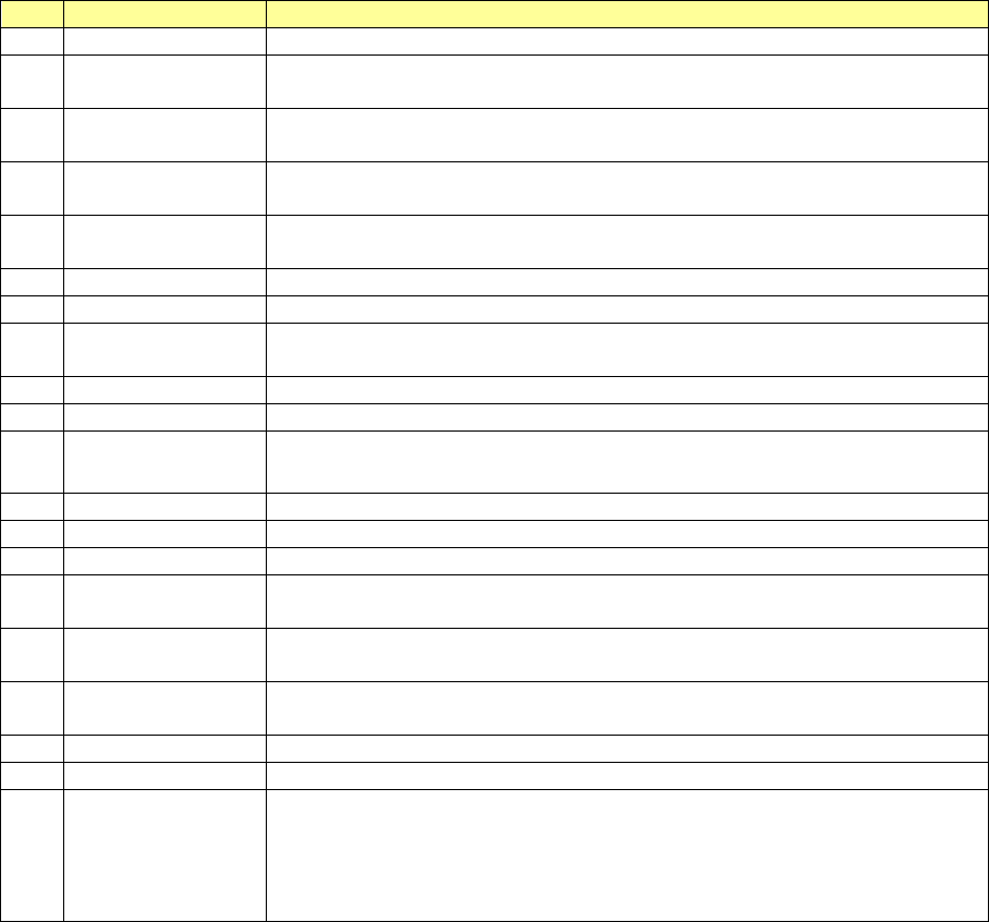
No.
Menu item
Description
1
Head
Shows the head number.
2 Total picked
Shows how many times the head picked up components.
(“Cmp. picked” + “Pick Error”)
3 Cmp. picked
Shows the number of components that were picked up with the head
successfully.
4 Cmp. placed
Shows the number of components that were placed on boards with the head
successfully.
5 Cmp. scrapped
Shows the number of components that were lost with the head.
(“Total picked” – “Cmp. placed”)
6
Pick Error
Shows how many times the head failed to pick up a component.
7
Cmp. fall
Shows how many picked components fell until they were placed on boards.
8 Cmp. takeout
Number of components taken back when components are placed and the nozzle
is raised.
9
LA recognition
Shows how many times a laser recognition retry over error occurred at the head.
10
Irregular dimensions
Shows how many times the system detected an irregularly shaped component.
11 Tombstone
Shows how many times the system judged that a component picked up by the
head stood on its side.
12
Posture
Shows how many times a component posture error occurred.
13
Laser angle error
Shows how many times a laser angle error occurred.
14
Vision Recog.
Shows how many times an image recognition error occurred.
15 Copla error
Shows the number of components whose lead float error or ball height error was
detected with the coplanarity unit.
16 Verify error
Shows how many times the system judged that a verify error, an SOT error or a
component direction error occurred.
17 Lead
Shows how many times the system judged that a lead bend error occurred during
component recognition.
18
Wrong Pick Pos
Shows how many times a wrong pick position error occurred.
19
Cmp. Remove
Shows how many times components were discarded.
20 Other error
Shows how many times the system judged that an error other than those above
occurred.
On RS-1/1R, count as other errors in the following cases.
- Vision Under the multi recognition, the bottom of the component can not be
within the recognition height range.