RS-1_instruction manual.pdf - 第471页
Part 1 B asic O peration Chapter 4 Cr eating a Produc tion Progra m 4- 136 (5) Feeder Option Set the calcu l ating met hod for the feeder type t o be used for optimizat i on and feeder layout . 1) Feeder type setti ng Fo…
Part 1 Basic Operation Chapter 4 Creating a Production Program
4-135
<Priority of layers>
The relation between layers is shown in the table below.
Priority Layer type
1 Placement layer
2 Component layer
3 Component type/height layer
If the system is not able to place a component on a board because components run out
during PWB production when the option “When components run out, production pauses” is
not selected on the “Production (Pause)” tab invoked from the “Operation option” screen, the
system skips the corresponding placement to continue the current PWB production. The
system places the skipped component finally after the production resumes by your
replenishing the feeder that caused a component run-out error. At this point, the production
conditions based on the component height may not be satisfied. Therefore, we recommend
that you select the option “Stop system on component run out” on the “Operation option”
menu when you select “Consider the component types and heights.”
2) Order placement from smallest to largest nozzle size:
When this item is checked off, components of the small-diameter nozzle are first placed at
optimization.
3) Specify group trays with same component type together
Regarding the same type tray components to be supplied to the MTC/MTS, specify whether
to arrange trays collectively or arrange them giving priority to the feed speed.
a) Group trays with same component type together:
Trays are arranged for each sane component type.
b) Arrange trays to optimize supply time:
Trays are arranged by giving priority to the feed speed.
Comp Type A
Comp Type A
A
Comp Type B
A
Comp Type C
Comp Type B
A
B
B
B
C
Comp Type C
A
C
B
C
C
When “Group trays with same
component type together” is
selected
Arrangement with supply
speed priority
Part 1 Basic Operation Chapter 4 Creating a Production Program
4-136
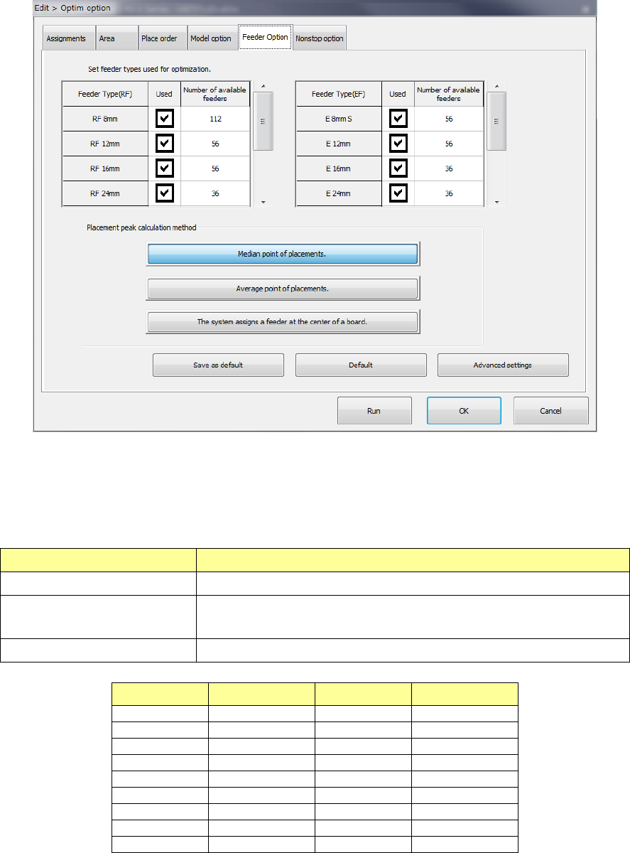
(5) Feeder Option
Set the calculating method for the feeder type to be used for optimization and feeder layout.
1) Feeder type setting
For an electric feeder that has two or more feeder types for the same tape width, set a
“feeder type used for optimization.” When you select two or more feeder types, the system
uses the optimal feeder among the selected feeder types to generate Pick data.
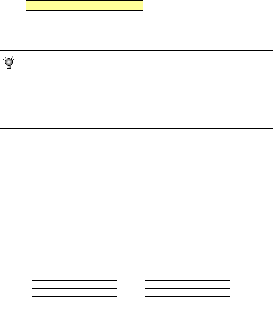
Item name Contents
Feeder Type (EF, RF) Shows the electric tape feeder type.
Used
Select whether the target feeder is used for optimization.
When checked on, the feeder is used for optimization.
Number of available feeders Set an upper limit to the number of target feeders used for optimization.
Feeder type Input range Feeder type Input range
RF 8 mm
1 - 112
E 8 mm S
1 - 56
RF 12 mm
1 - 56
E 12 mm
1 - 56
RF 16 mm
1 - 56
E 16 mm
1 - 36
RF 24 mm
1 - 36
E 24 mm
1 - 36
RF 32 mm
1 - 28
E 32 mm
1 - 28
RF 44 mm
1 - 22
E 44 mm
1 - 22
RF 56 mm
1 - 18
E 56 mm
1 - 18
RF 72 mm
1 - 12
-
-
RF 88 mm
1 - 10
-
-
If the number you set on the screen for setting the number of components exceeds the total
of the number set in the “Number of available feeders” for the electric tape feeder when you
press the <Run> button, the Optimization utility cannot be executed.
Part 1 Basic Operation Chapter 4 Creating a Production Program
4-137
2) Calculating method for placement peak point
Specify the calculating method for the starting point of feeder layout.
a) Arrange a feeder in the mid-point of placement points
Arrange a feeder in a position close to the placement point that is a mid-point counted
from the smallest coordinate value when each placement point is arranged in the order
starting from the smallest coordinate value.
b) Arrange a feeder in the mean point of placement points.
Arrange a feeder in the position closest to the mean coordinate value of all the placement
points.
c) Arrange a feeder in the center point of the PWB.
Arrange a feeder in the position corresponding to the center coordinates of the PWB.
• When there are many components and placement points are made uniform over the
PWB, both cases leads to the same result.
• Generally, when a part of placement points is separated among all the placement
points, "Mid-point" is advantageous. Otherwise, "Mean point" tends to be
advantageous.
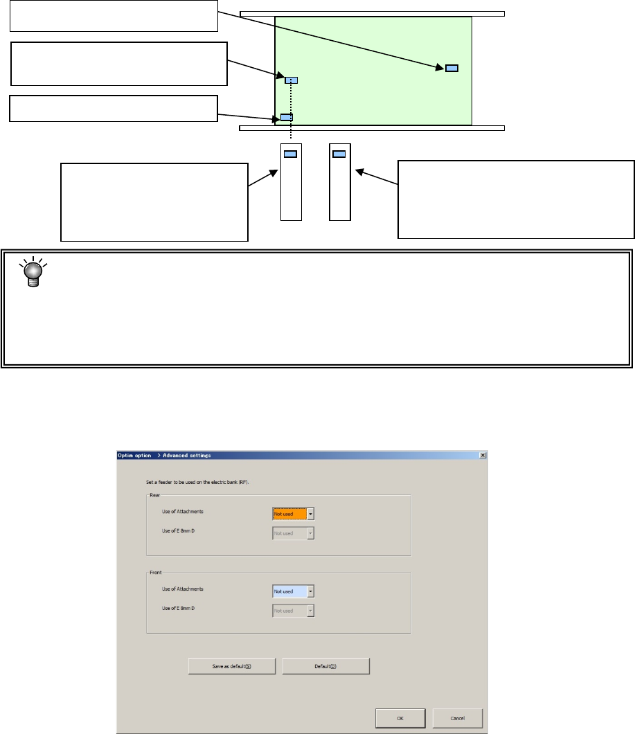
3) Advanced settings
When you assign a feeder, specify whether to assign an EF type feeder with using the
attachment.
When the attachment is not used, the system does not assign any EF type feeder.
The 2nd closest placement point
(Mid-point in this case)
The 3rd closest placement point
The first closest placement point
Feeder layout when "Feeder
layout in the mid-point" is
selected. (Layout on the
base of the mid-point)
Feeder layout when "Feeder layout in
the mean point" is selected
(Located on the basis of the mean
coordinates among placement points)