RS-1_instruction manual.pdf - 第786页
Part 2 D etaile d Descript ion of E ach Functi on Chapter 9 M anual Control 9- 14 9.4 Co n v e yo r 9.4.1 Conveyor control W hen yo u sel ec t [Convey or (C)] - [C onvey or control (V) ] form th e pu ll - down menu, or w…
Part 2 Detailed Description of Each Function Chapter 9 Manual Control
9-13
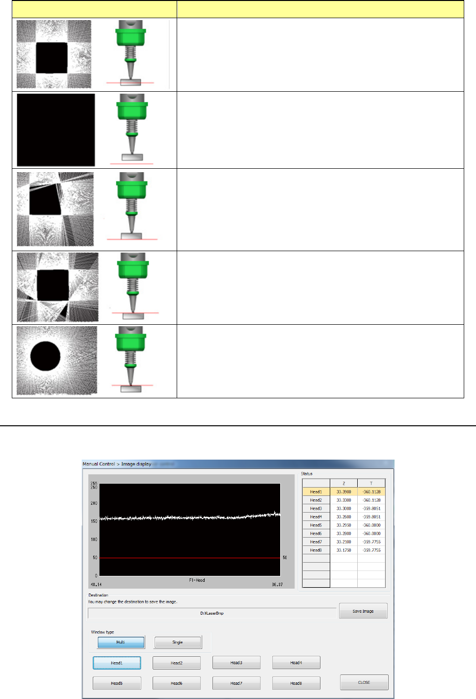
String art and the laser height Description
This indicates the appropriate laser height. The laser sensor
obtained the shape of a component correctly. When the laser
sensor obtains the component shape, it returns the SWEEP
recognition result to the system.
If a component is not located at a position that is irradiated with
laser, the system does not obtain any edge data. Therefore,
any string art is not drawn, and the screen becomes black. In
this case, the laser sensor fails to perform SWEEP, and returns
a no-component error to the system.
If the laser height is almost the same as the height of the
bottom side of a component, the component does not shield
laser sufficiently and the sensor does not obtain the edge data
at several positions. Therefore, the string art shape becomes
inappropriate, and the laser sensor fails to perform SWEEP
and returns a recognition error to the system.
If the laser height is almost the same as the height of the
boundary between the top side of a component and the nozzle,
the component does not shield laser sufficiently in the same
way as the above. Therefore, the laser sensor fails to
perform SWEEP.
If the laser height is the same as not the height of a component
but that of the nozzle tip, the string art shows the shape of the
nozzle tip.
9.3.3.7 Control item: Image display
This button displays the image data sensed with the laser sensor for the selected head.
When the control item “Image display” is selected, press the <Exec> button for control.
Part 2 Detailed Description of Each Function Chapter 9 Manual Control
9-14
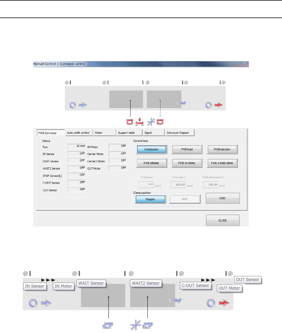
9.4 Conveyor
9.4.1 Conveyor control
When you select [Conveyor (C)] - [Conveyor control (V)] form the pull-down menu, or when you
select the [Conveyor control] command button, the “Conveyor control” screen appears.
When you select [Conveyor] → [Conveyor control] in the menu, the conveyor control dialog is
displayed.
The status of each conveyor sensor/conveyor motor is displayed in the upper part of the screen.
The conveyor stopper and stopper sensor on the IN side are displayed when the option stopper is
valid.
The tool hint is displayed by putting the cursor on the sensor display figure. The above figure
displays each stop sensor/motor sensor.
For the display figure of each sensor, refer to the table on the next page.
Part 2 Detailed Description of Each Function Chapter 9 Manual Control
9-15
You can select a control tab by using a pushbutton in the center of the screen.
Their details will be described later. Refer to “9.4.1.1 Control tab: PWB conveyor or later.
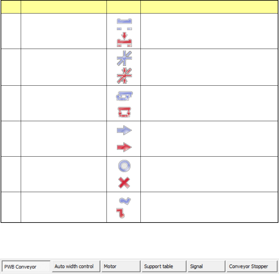
No. Display item Symbol Description
1
Support table stopper
The support table stopper is set to OFF.
Support table stopper is set to ON.
2
Support table origin sensor
The support table origin sensor is set to OFF.
The support table origin sensor is set to ON.
3
IN buffer selector/OUT buffer
selector
The IN/OUT buffer selector is set to OFF.
The IN/OUT buffer selector is set to ON.
4
Ready IN/Ready OUT
The ready IN/ready OUT signal is set to OFF.
The ready IN/ready OUT signal is set to ON.
5
Board available IN/Board
available OUT
The board available IN/OUT signal is set to OFF.
The board available IN/OUT signal is set to ON.
6
Conveyor stopper
The conveyor stopper is set to OFF.
The conveyor stopper is set to ON.