RS-1_instruction manual.pdf - 第969页
Part 2 D etaile d Descript ion of E ach Functi on Chapter 12 Handling th e Optional Device s 12 - 85 Wh en you se lect the < Low load> but ton on the “ Pick Con diti on ” tab/the “ Pl ace Co ndi ti on ” tab, t he m…
Part 2 Detailed Description of Each Function Chapter 12 Handling the Optional Devices
12-84
12.13.5 Program Editor
12.13.5.1 Load control setting
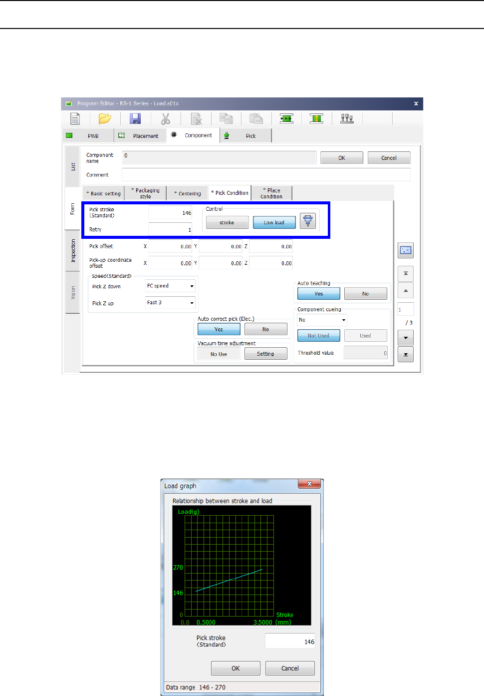
When the selected nozzle is to be used to control load, the “Control” button displayed on the “Pick
Condition” tab and the “Place Condition” tab allows you to select whether to control load or not.
When you select the <Low load> button, the input unit for the menu items “Picking stroke” and
“Placing stroke” is changed from “mm” to “g.”
When the selected nozzle is to be used to control low control, the graph button is enabled on the
screen. When you press this graph button, the graph showing the relation between the push-in
amount (stroke) and the load value appears on the screen.
The input lower limit and the input upper limit of the push-in amount (stroke) are displayed on the
horizontal axis.
The input lower limit and the input upper limit of the stroke (load) are displayed on the vertical axis.
Part 2 Detailed Description of Each Function Chapter 12 Handling the Optional Devices
12-85
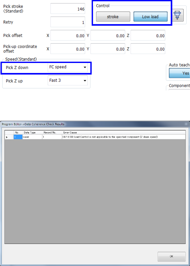
When you select the <Low load> button on the “Pick Condition” tab/the “Place Condition” tab, the
menu item “Pick Z down” /“Place Z down” is set to “FC speed” (Force Control speed).
If the menu item “Pick Z down”/”Place Z down” is set to the speed other than “FC speed” and load is
entered in the “Pick stroke”/”Placing stroke” field in gram, a consistency check causes an error.
Part 2 Detailed Description of Each Function Chapter 12 Handling the Optional Devices
12-86
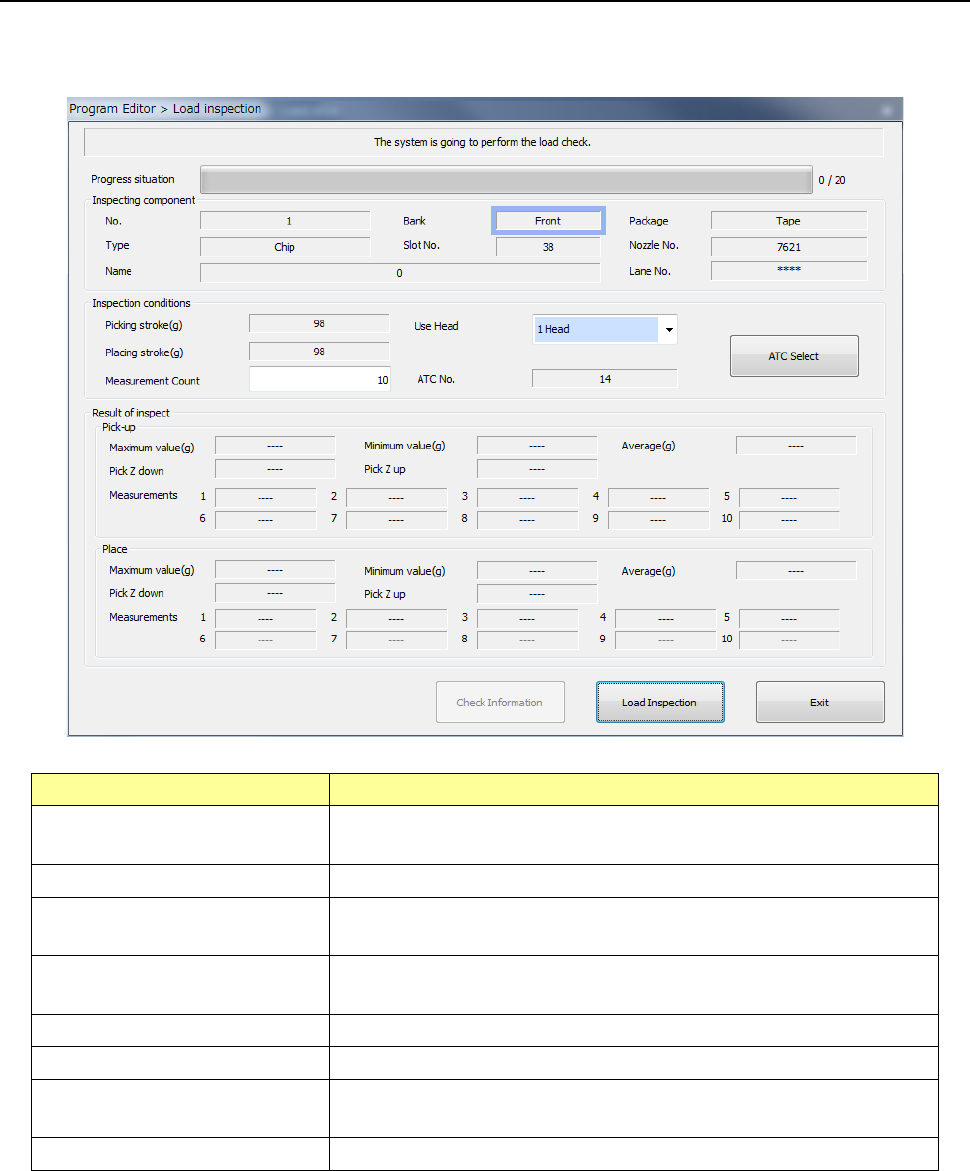
12.13.5.2 Editing sub-functions
Start up the “Program Editor,” select the “Component” data screen and then [Meas/Insp] command.
Next, select the [Load inspection] command from the displayed menu.
Item
Description
Component being inspected
Displays the detailed data on a component whose load is to be
inspected.
Inspection conditions
Displays the conditions for inspecting load.
Picking stroke (g)
Displays the push-in load value to be applied when the machine is
picking up a component.
Placing stroke (g)
Displays the push-in load value to be applied when the machine is
placing a component on a board.
Use Head
You can select a head to be used to inspect load.
Measurement Count
Specify how many times to inspect load.
ATC No. Displays the ATC No. of the nozzle to be used when the machine
inspects load.
Result of inspect
Displays the load inspection results.
See Section 4.5.7.6 “Load inspection” for details.