RS-1_instruction manual.pdf - 第400页
Part 1 B asic O peration Chapter 4 Cr eating a Produc tion Progra m 4- 65 2) Vision c entering When you se lect the “ Cen tering ” tab, the fol lowing s creen appear s . ① Noz zle No. ② V acuum level Set these it ems as …
Part 1 Basic Operation Chapter 4 Creating a Production Program
4-64
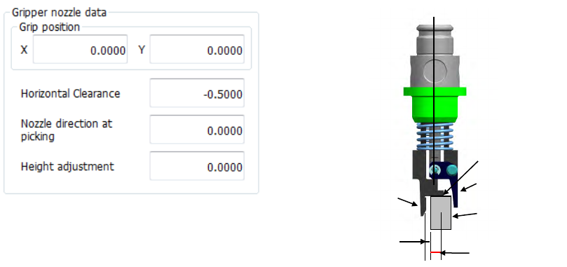
⑤ Gripper nozzle data
Grip position:
Enter a negative value (“-a”) into the “Y” field as the offset from the center of a component to
the side against which a component is pushed (“a”). Do not enter any value other than “0”
into the “X” field.
Horizontal Clearance:
Enter a negative value as the clearance between the side against which the arm on the
gripper nozzle fixed side is pushed and a component (“b”).
Usually, set the default value that is automatically input.
Nozzle direction at picking:
Specify the nozzle direction when the nozzle picks up a component that is supplied at 0
degrees. Specify one of the directions: 0, 90, 180 and 270 degrees.
Height adjustment:
Correction value (clearance between c and the top surface of the component) Normally, set
“- 0.5 mm” to keep a component horizontal.
Grip position (a)
Horizontal
clearance (b)
Component
C
Fixed arm
Swing arm
Part 1 Basic Operation Chapter 4 Creating a Production Program
4-65
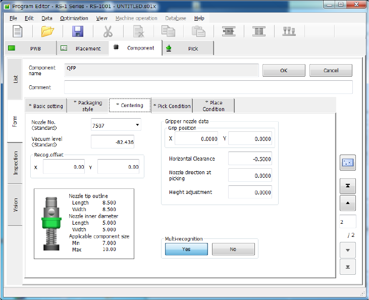
2) Vision centering
When you select the “Centering” tab, the following screen appears.
① Nozzle No.
② Vacuum level
Set these items as described in “1) Laser centering.”
Part 1 Basic Operation Chapter 4 Creating a Production Program
4-66
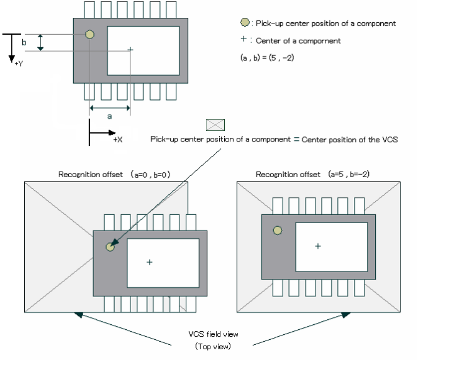
③ Recog. Offset
The system moves the pick-up center position of a component (normally the center of a
component) to the center position of the VCS to center the component with the VCS.
However, since the system cannot pick up the center of a component such as an MCM
(Multi Chip Module) and the component position may be located outside the VCS field view
range, it may not be able to center the component with the VCS. In this case, enter offset
values (a, b) as shown below to ensure normal recognition.
Example: Data entry
④ Gripper nozzle data
Set this item as described in “1) Laser centering.”
⑤ S-VCS
Specify whether to recognize a component with an S-VCS or not.
VCS field of view (top view)