RS-1_instruction manual.pdf - 第823页
Pa r t 2 Det ai l ed Des c r i pti on o f Ea c h Fu nc ti on Chapter 10 M ach i ne Manage m e nt Infor m ation 10 - 10 2) <Exc hang e f req uency setup /War ning /E rror lev el set ting s> b utton Thes e butt ons a…
Part 2 Detailed Description of Each Function Chapter 10 Machine Management Information
10-9
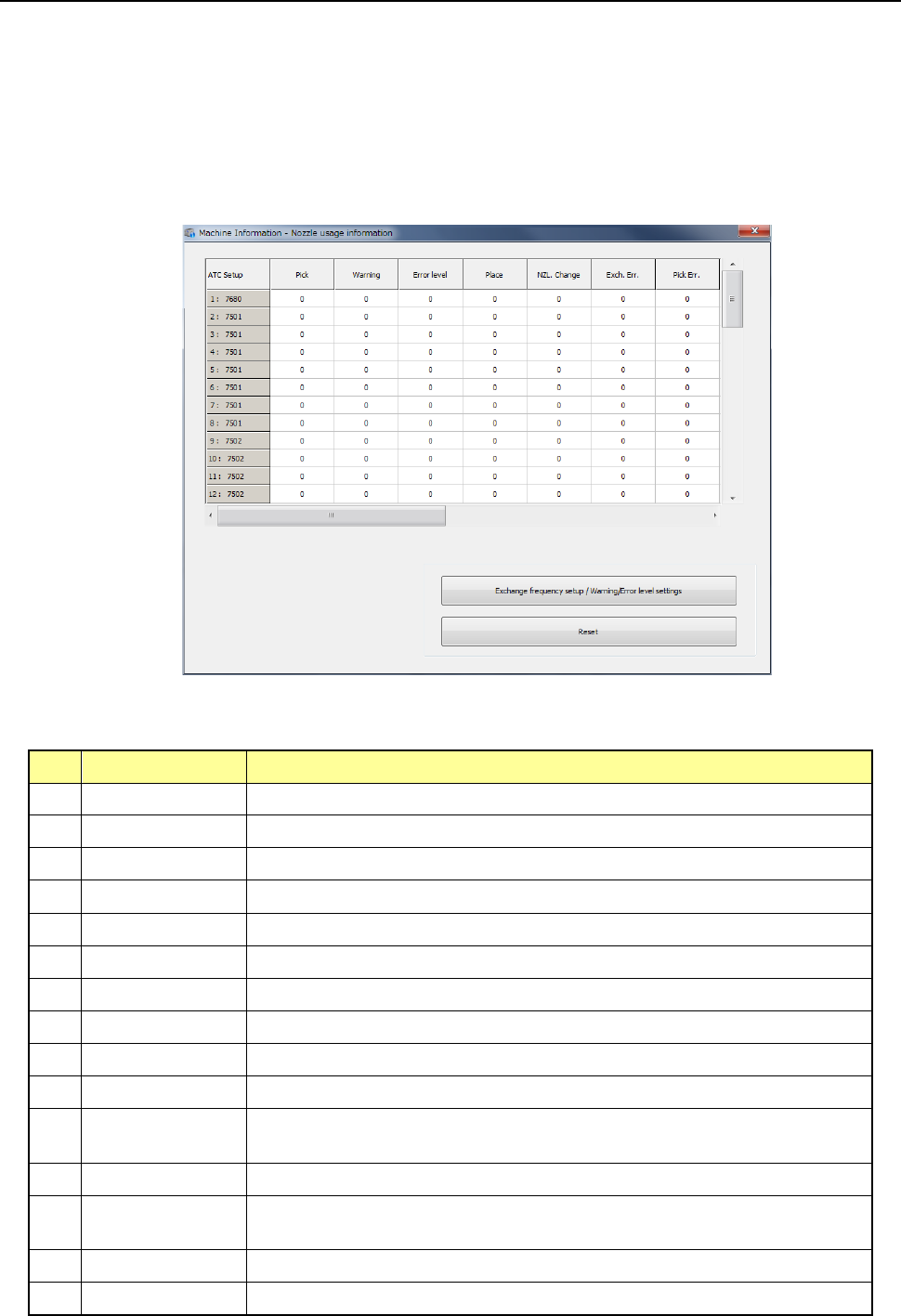
10.3.4 Operation Information of each nozzle
The operation information of each nozzle is controlled according to the ATC number.
When you change the nozzle assignment on the ATC, you have to rewrite the corresponding
nozzle data with the command provided on this screen.
(1) Displayed screen
When you select [Machine] – [Nozzle usage information] in the main menu, the nozzle usage
information screen appears. This screen is changed over to the information on each bank
by pressing the <Select device> button.
1) List
The number of operations and the related data on each nozzle are displayed as a list here.
No.
Item
Description
1 Pick Counts how many times the nozzle picked a component totally.
2 Place Counts how many times the nozzle placed a component successfully.
3 NZL Change Counts how many times the nozzle was replaced successfully.
4 Warning Displays the warning level.
5 Error level Displays the error level.
6 Exch. Err. Counts how many times a replacement error occurred per a nozzle.
7 Pick Err. Counts how many times a pick-up error occurred per a nozzle.
8 Retry Counts how many times a component pick-up retry over error occurred.
9 LA Recog Counts how many times a laser recognition error occurred.
10 Chip Counts how many times a chip rise error occurred.
11 Dimension
Counts how many times an irregular-shaped component error occurred at
the nozzle.
12 Posture Counts how many times a component posture check error occurred
13 Presence
Counts how many times a component presence check error occurred
before placement of a component.
14 Vision recognition Counts how many times a vision recognition error occurred.
15 Sliding Fail Counts how many times sliding failed.
Part 2 Detailed Description of Each Function Chapter 10 Machine Management Information
10-10
2) <Exchange frequency setup/Warning/Error level settings> button
These buttons are described in the sub-sections later.
3) <Reset> button
This button is described in the sub-section later.
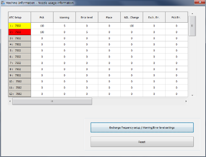
(2) Screen displayed when a warning is issued or an error occurs
When a value in the “Pick” cell exceeds that in the “Warning” cell, the nozzle is displayed in
yellow. When a value in the “Pick” cell exceeds that in the “Error level” cell, the nozzle is
displayed in red.
The signal light lighting condition does not change.
Part 2 Detailed Description of Each Function Chapter 10 Machine Management Information
10-11
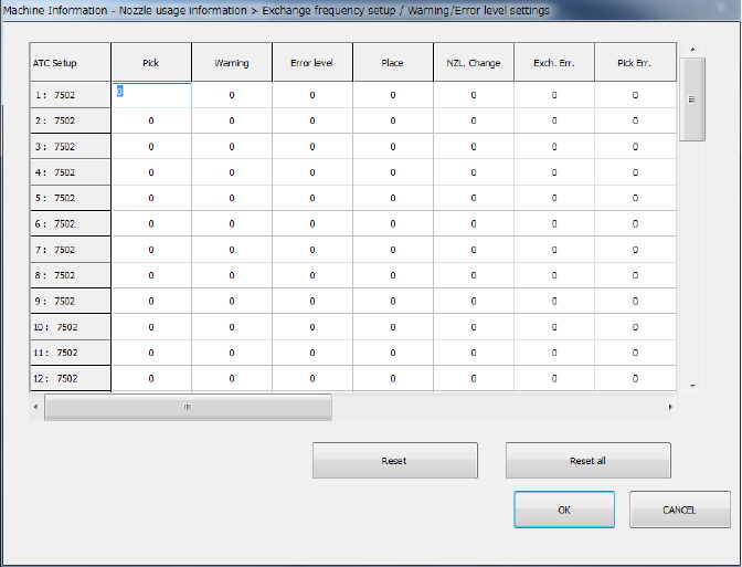
(3) Exchange frequency setup
When you press the <Exchange frequency setup> button or select [Set] – [Setting – Nozzle
usage information] in the menu, the exchange frequency setup screen appears. When the
STC nozzle arrangement was changed, it is possible to change the data on each nozzle.
The setting can be executed when the user level is set to Serviceman.
1) Press the item to be updated or press a number key after moving the cursor by the
direction key of the software keyboard, and the target cell will be active so that it can be
edited.
2) If you press the <ESC> key when the cell is active, the data being changed is cancelled.
3) If you press the <ENTER> key or the <TAB> key when the cell is active, a value you
have entered in the cell is validated.
4) Press the <OK> button to check data and close the exchange frequency setup screen.
5) Press <CANCEL> to revert nozzle usage information to the original and close the
exchange frequency setup screen.