RS-1_instruction manual.pdf - 第347页
Part 1 B asic O peration Chapter 4 Cr eating a Produc tion Progra m 4- 12 Example : When the lower lef t corner is specified as a P WB po sition referenc e (Unit: mm) ① For boar d and PWB tr an sport dir ecti on of L → R…
Part 1 Basic Operation Chapter 4 Creating a Production Program
4-11
(2) Single circuit PWB
Single-circuit PWB means a PWB on which only one circuit exists.
1) PWB dimensions
Enter the dimensions of a PWB here.
If the machine is supplied with a
dummy PWB, enter the dimensions
of this PWB also.
The same direction as the transport
direction is X and the direction
perpendicular to the transport direction is Y.
2) PWB layout offset
Enter the length from the PWB
position reference to the end point
of the PWB layout.
Enter the distance from the PWB
origin defined by the CDA or other
tool to the reference position (PWB
layout endpoint) if the specified
origin (the CAD origin or an origin
that is unique to a user) must be
used as the PWB origin, for
example, in a case in which CAD
data is used.
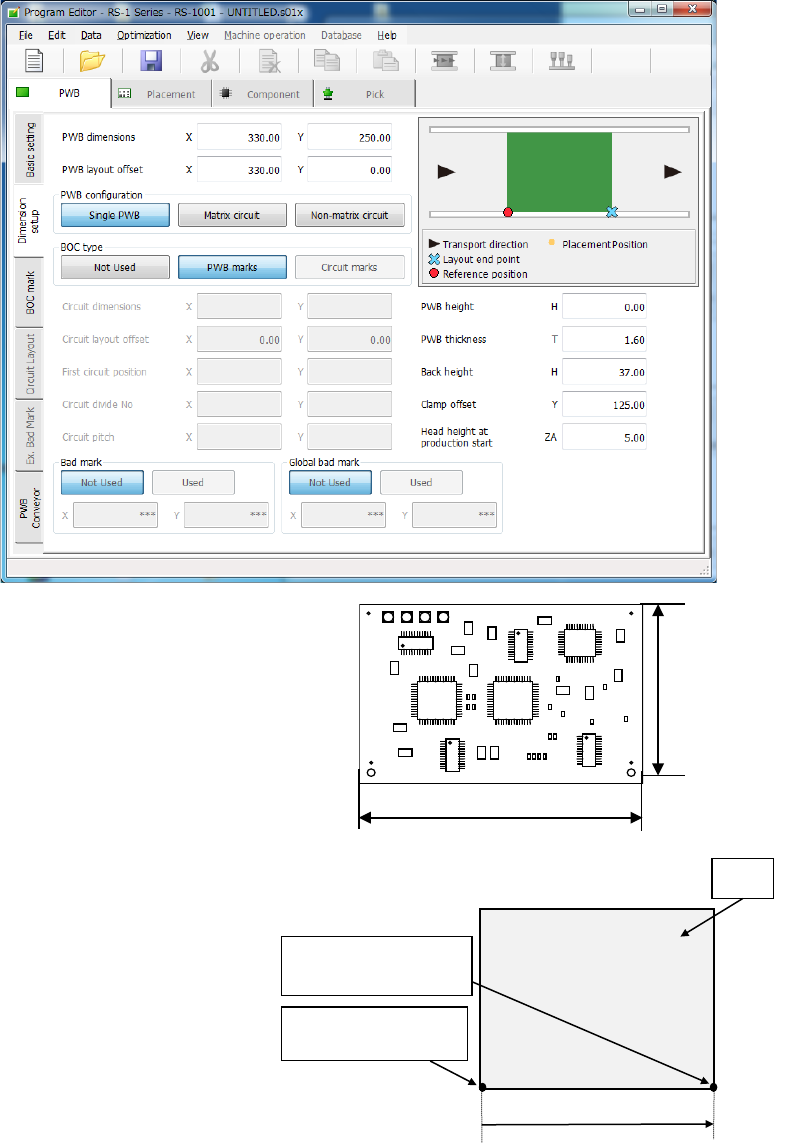
When transport is performed by front reference and the PWB flow direction is left to right,
the PWB layout end point is “reference position.” When the PWB reference position is at
the left lower corner of the PWB, enter the (Xb, 0) value in each of the X and Y coordinates
of the PWB layout offset. The Xb is a positive value.
PWB reference
position
PWB
Yb = 0
Xb
PWB layout endpoint
(Reference position)
Dimension X
Dimension Y
Part 1 Basic Operation Chapter 4 Creating a Production Program
4-12
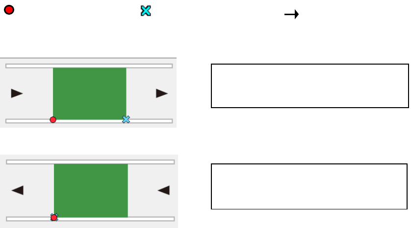
Example: When the lower left corner is specified as a PWB position reference (Unit: mm)
① For board and PWB transport direction of L → R:
② For board and PWB transport direction of R → L:
3) PWB configuration
For this item, select [Single circuit].
After the multi-circuit matrix or multi-circuit non-matrix is changed into the single circuit
matrix, single circuit expansion is performed.
At this time, a confirmation message is displayed.
4) BOC type
“BOC” is abbreviation of Board Offset Correction, and is a mark for correcting a component
placement position that helps the system to place a component on a board more accurately.
(It is called a “fiducial mark” also.)
◆ Not Used: Select this button when any BOC mark is not used.
◆ PWB marks: Select this button to use BOC marks on a board to correct the component
placement coordinates.
◆ Circuit marks: This button cannot be selected for a single-circuit PWB.
5) Circuit dimensions
6) Circuit layout offset
7) First circuit position
8) Circuit divide No.
9) Circuit pitch
You do not have to set these items for a single-circuit PWB (these items are disabled).
You have to set them for a multi-plane PWB (“Matrix circuit” or “Non-matrix circuit”).
PWB dimensions X=165 Y=125
PWB layout offset X=165 Y=0
PWB dimensions X=165 Y=125
PWB layout offset X=0 Y=0
:Reference position
:
Transport direction
:Layout end point
Part 1 Basic Operation Chapter 4 Creating a Production Program
4-13
10) PWB height
Enter the length of the top plane of the PWB from the transport reference plane (reference
height. This is the initial value (= 0.00) of the Z axis).
Usually, enter the initial value. When the transport reference plane is different in height
from the PWB top plane, enter the PWB height.
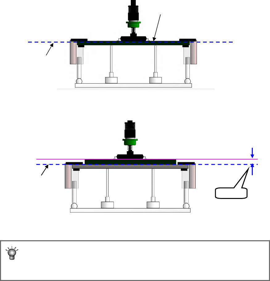
Example: Odd-shape PWBs or flexible PWBs are manufactured by piling the jig (carrier
board). In this case, enter “+t” for the PWB height.
• Normal case(Transport reference plane = PWB top plane height)
• Using the jig (Transport reference plane ≠ PWB top plane height)
If “+t” is not entered in this case, the component is pushed over the placement plane (by the
length of t) at placement, thereby damaging the component.
The nozzle height at component placement depends on the PWB height.
Accordingly if an incorrect value is set, the placement may lose uniformity. (The
component is released from a position remote to the PWB or the component is
pushed in too much in the PWB.)
Transport reference plane
PWB top plane height
Transport reference plane
PWB top plane height
Jig (carrier board)
+t