RS-1_instruction manual.pdf - 第447页
Part 1 B asic O peration Chapter 4 Cr eating a Produc tion Progra m 4- 112 The condit ions for recog nizing divided images of a compon ent vary depending on component types. VCS 54mmFOV (54 - mm field of view) 27mmFOV 10…
Part 1 Basic Operation Chapter 4 Creating a Production Program
4-111
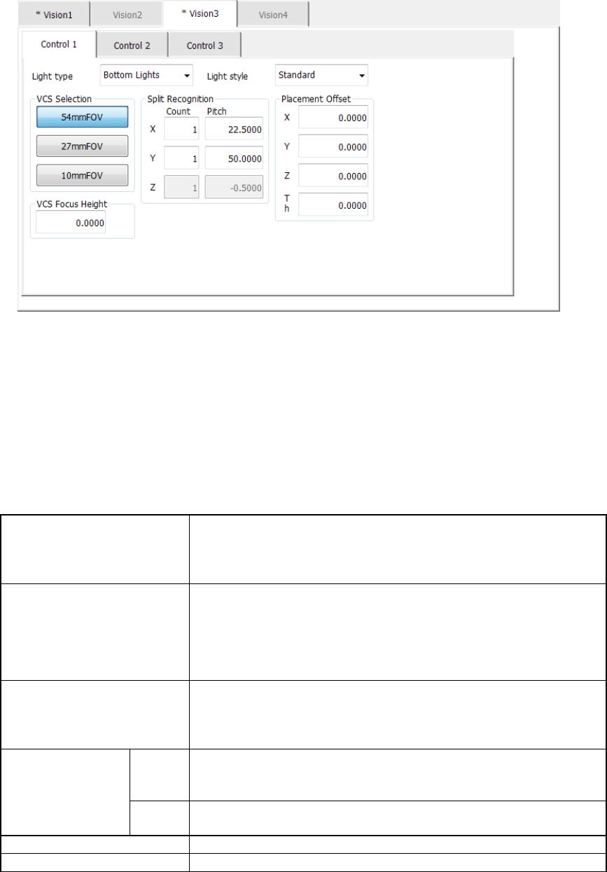
(13) Light control data screen
When you select the “Vision 3” tab, the following screen opens.
The “Control 1” tab allows you to set the light used for a component whose image is divided
to be recognized (split recognition or division recognition).
Set this type of light in the following order:
1. Set a VCS used to recognize a component.
2. Specify the split recognition.
3. Specify the light type and light style (applicable when “Bottom Lights” or “Side Lights” is
selected as the “Light type”).
4. Make other settings.
Light type
Select the light type:
- Bottom Lights
- Back Lights
- Side Lights
Light style
Select the light type in details.
- Bottom
- CBGA
- Side
- Blue
- Standard
- LGA
- Red
- Fine
VCS Selection
Select a VCS used to recognize a component.
- 54mmFOV
- 27mmFOV
- 100mFOV
Split Recognition
Count
Set the number of divisions in each direction, X, Y and Z.
The input range of the number of divisions are: X (1 to 2),
Y (1 to 3) and Z (1 to 2).
Pitch
Set the distance a VCS travels. The value you can enter
here varies depending on the selected VCS.
Placement Offset
Placement offset for each component
VCS Focus Height
Specify the height a VCS recognizes.
Part 1 Basic Operation Chapter 4 Creating a Production Program
4-112
The conditions for recognizing divided images of a component vary depending on component
types.
VCS
54mmFOV (54-mm field
of view)
27mmFOV 10mmFOV
Split
Recognition
X×Y
1×2
2×1
1×3 2×2
1×2
2×1
1×3 2×2
1×2
2×1
2×2
Component
type
Square chip × × × × × × × ×
Elec. Cap. (aluminum
electrolytic capacitor)
× × × × × × × ×
GaAsFET × × × × × × × ×
SOP ○ × ○ ○ × ○ × ×
HSOP × × × × × × × ×
SOJ × × × × × × × ×
PLCC(QFJ) × × × × × × × ×
PQFP(BQFP) ○ × ○ ○ × ○ × ×
TSOP ○ × ○ ○ × ○ × ×
TSOP2 ○ × ○ ○ × ○ × ×
BGA *1 ○ × ○ ○ × ○ × ×
FBGA *1 ○ × ○ ○ × ○ ○ ○
Outline recog.
(outline-recognition
component)
○ ○ ○ × × × × ×
GNRL. Vision
(general-purpose vision
component)
○ ○ ○ ○ ○ ○ ○* 2 ○* 2
CONN (unidirectional
lead connector)
○ ○ × ○ ○ × × ×
CON2 (bidirectional
lead connector)
○ ○ × ○ ○ × × ×
CONZ (Z-lead
connector)
○ ○ × ○ ○ × × ×
CONX (extended-lead
connector)
× × × × × × × ×
SKT-J (J-lead socket) × × × × × × × ×
SKT-G (gull-wing
socket)
× × × × × × × ×
SKT-B (socket with a
bumper)
× × × × × × × ×
QFN × × × × × × × ×
*1 For BGA and FBGA components, the split recognition may vary depending on the
recognition type. The split recognition is applicable only when the components are all balls
or all lands.
*2 Split recognition of a general-purpose vision component with the 10-mm field of view
supports a ball component only.
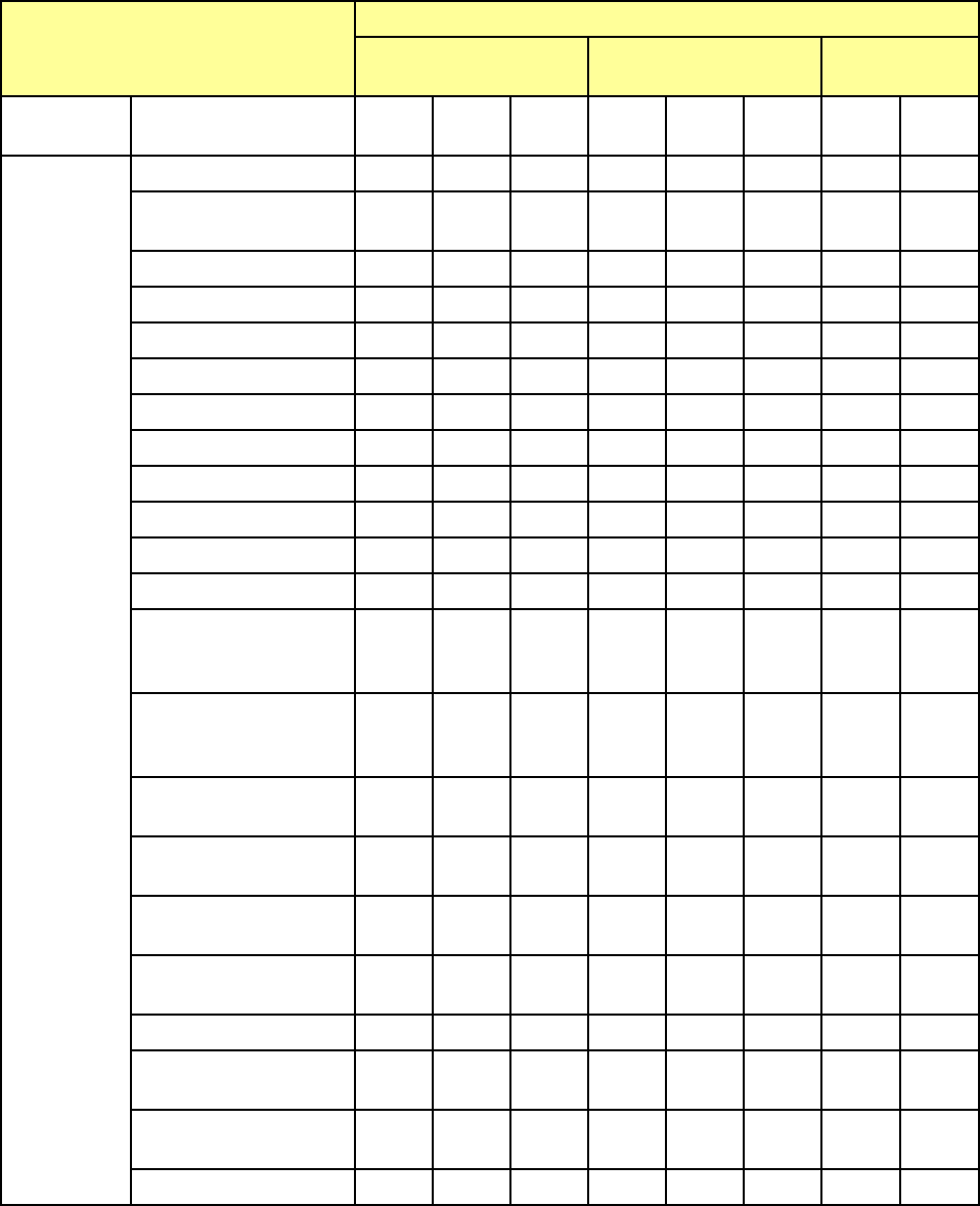
Part 1 Basic Operation Chapter 4 Creating a Production Program
4-113
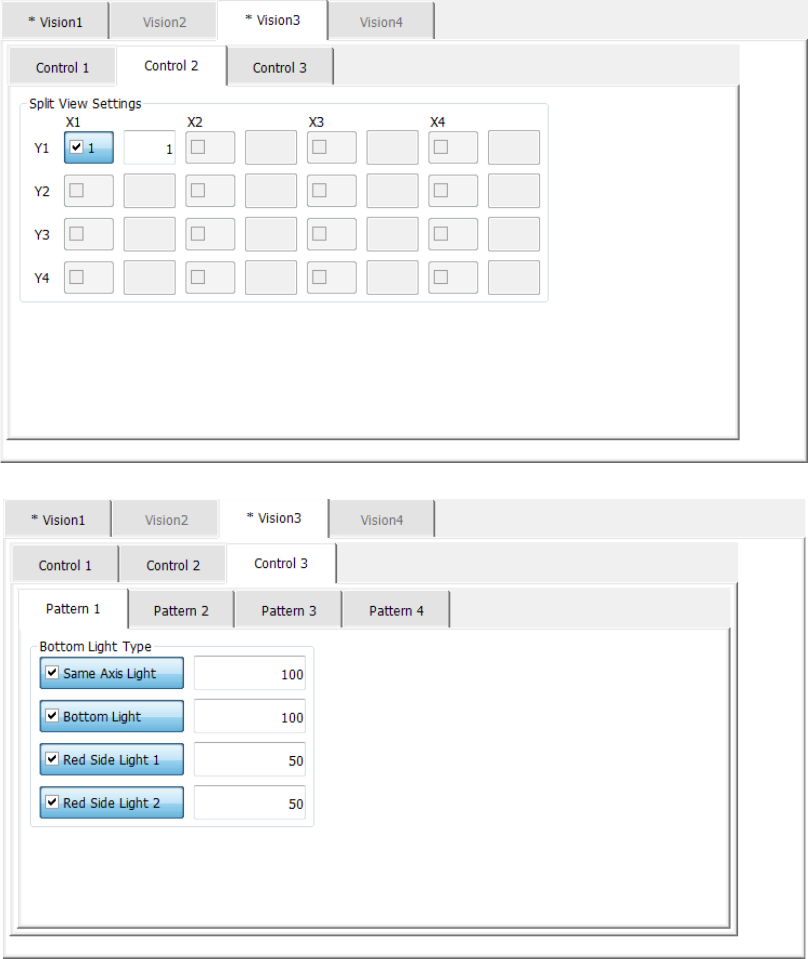
The “Control 2” tab and the “Control 3” tab are screens that allow you to set the data on lights used
to recognize a component with a VCS in details.
These tabs are displayed as shown below according to selection of the “Light type” of the vision
control data.
1) For the bottom light
The light control data (bottom light) screen allows you to set the input value of the bottom
light.
The light control data (bottom light) screen is shown below.