RS-1_instruction manual.pdf - 第171页
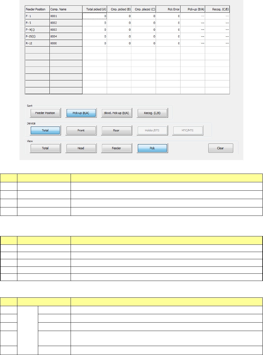
Part 1 B asic O peration Chapter 2 Pr oduction 2- 60 No. Menu item Description 1 Feeder Pos ition Shows the c omponent s upply position. For a stick feed er , the lane is displayed i n parentheses. 2 Comp. Nam e Displays…
Part 1 Basic Operation Chapter 2 Production
2-59
4) Management Info (Pick)
The system shows “the pick-up ratio per component supply position (Pick-up ratio = Number
of pick-ups / (Number of pick-ups + Number of pick-up errors))” on the screen.
The pick-up ratios are normally displayed on the screen in the order of ascending
pick-up ratios.
“Sort”: Select how to sort the pick-up ratios displayed in the list.
No.
Menu item
Description
1
Feeder Position↓
Sorts the pick-up ratios in the order of descending feeder positions to display them.
2
Pick-up (B/A)↓
Sorts the pick-up ratios in the order of ascending pick-up ratios to display them.
3
Bkwd. Pick-up (B/A)
Sorts the pick-up ratios in the order of descending pick-up ratios to display them.
4
Recog. (C/B)↓
Sorts the pick-up ratios in the order of ascending recognition ratios to display them.
“View Bank” allows you to select a bank on which a component is located to be displayed in the list
of the screen.
No.
Menu item
Description
1
Tot al
Shows all components.
2
Front
Shows only components set on the front bank.
3
Rear
Shows only components set on the rear bank.
4
Holder
Shows only components set on the holder or the DTS.
5
MTC/MTS
Shows only components set on the MTC or the MTS.
“View” allows you to change the displayed management information.
No.
Menu item
Description
1
View
Tot al
Shows the total management information.
2
Head
Shows the production management information per head.
3
Feeder
Shows the production management information per feeder.
4
Pick
Sorts the component pick-up rates at each component supplied position and
shows them.
5 Clear Clears the production management information.
Part 1 Basic Operation Chapter 2 Production
2-60
No.
Menu item
Description
1 Feeder Position
Shows the component supply position.
For a stick feeder, the lane is displayed in parentheses.
2
Comp. Name
Displays the name of a component.
3
Total picked (A)
“Cmp. picked” + “Pick Error”
4
Cmp. picked (B)
Displays the number of components that were picked up successfully.
5
Cmp.placed (C)
Displays the number of components that were placed on boards successfully.
6
Pick Error
Displays how many times the system failed to pick up a component.
7 Pick-up (B/A)
Displays the ratio of successful pick-ups.
“Pick-up” = “Cmp. picked” / (Cmp. picked” + “Pick Error”)
8 Recog. (C/B)
Displays the recognition ratio of components that were picked up successfully.
“Recog.” = “Cmp. placed” / “Cmp. picked”
• Updating the data
♦ During PWB production (while the system is producing a PWB):
Any data is not updated during PWB production. When you press a button, or when you
display the screen again, data is updated.
♦ While PWB production is suspended:
Data is automatically updated.
Managing the production management information
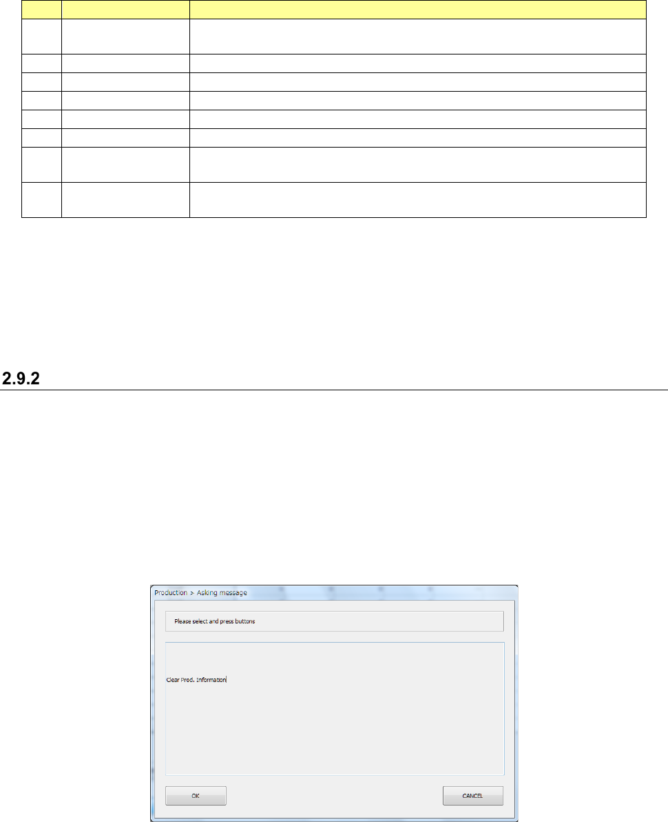
1) <Clear> button
To clear the production management information, select the <Clear> button in the “View”
column.
Or, select the [Program] command from the “Product” menu, and then the [Management Info
is cleared] command.
The “Asking message” screen that asks you whether to clear the production conditions
appears.
When you press the <OK> button, the system clears the production management information.
When you press the <CANCEL> button, the system does not clear the production
management information.
2) Saving the production management information
When you execute the [Save] command or the [Save as] command on the “File” menu after
PWB production, you can save the production management information in a file.
When you save a production program in response to the production-quit message displayed
after PWB production, you can the production management information also.
Part 1 Basic Operation Chapter 2 Production
2-61
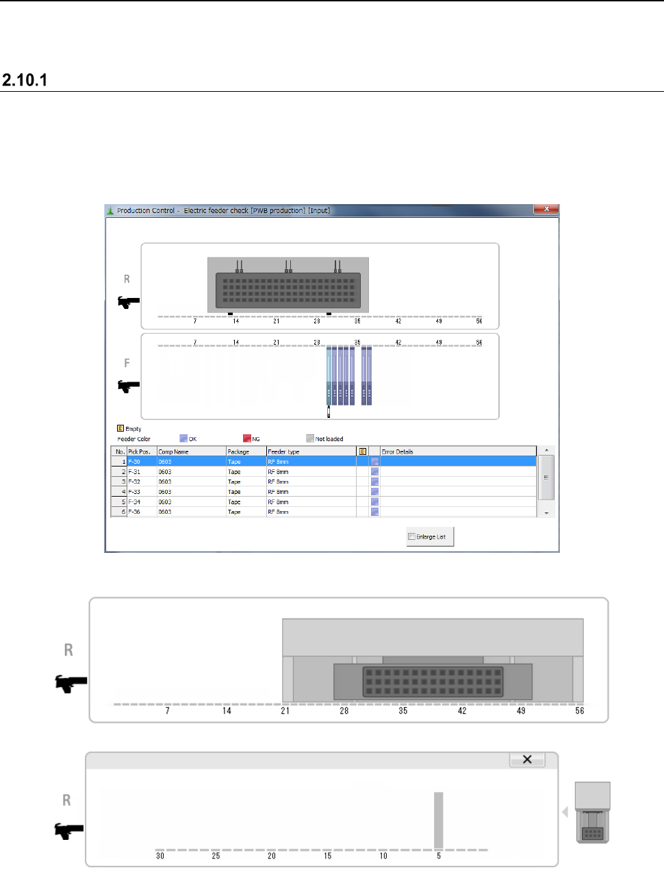
2.10 Electric feeder check
In the electric feeder check, the system checks whether or not correct components are put on the
electric feeder set for the current production program and displays the check results.
“Electric feeder check” screen
(1) “Electric feeder check” menu
Click the [Window] menu command on the “Product” menu and select the [Electric feeder
check].
(2) Contents
When a TR8SR is used as a component supply device, the TR8SR image is displayed on the
screen as shown below.
When you touch the displayed TR8SR image, the enlarged TR8SR image is displayed.
To return to the original TR8SR image screen, touch “×” or the TR8SR image displayed on the
right side of the screen.