RS-1_instruction manual.pdf - 第581页
Part 1 B asic O peration Chapter 4 Cr eating a Produc tion Progra m 4- 246 4) Light MEAS. If a component connect be recognized with the defa ult lighting brightne ss, the optimum lighting con di tions ar e obtained. • Li…
Part 1 Basic Operation Chapter 4 Creating a Production Program
4-245
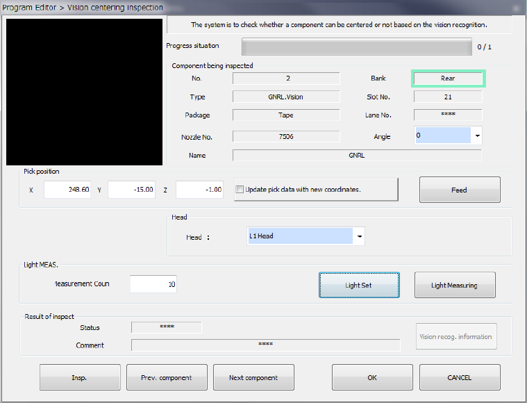
(3) Operations for vision recognition inspection
When you select the [Meas/Insp] command from the Program Editor menu, and then the
[Recognize] command, the following screen appears.
1) Component being inspected
Information on a component to be inspected with a VCS is displayed here.
2) Pick position
The component pick-up position is displayed here. You can change the pick-up position to
that of the previous or next alternative component.
If there is no Pick data created, each menu item is not displayed. So, you cannot change
the component pick-up position, feed the component, or perform the teaching operation.
You can enter a component pick-up position manually or by teaching operation.
● Update pick data with new coordinates.
Check off this check box to save the taught result into Pick data.
When unchecked, the displayed coordinates are used to pick up the current component
only.
● <FEED> button
The system knocks the feeder once to feed a component.
3) Head
A head to be used for inspection can be selected.
Select a head to be used in the combo box list.
Part 1 Basic Operation Chapter 4 Creating a Production Program
4-246
4) Light MEAS.
If a component connect be recognized with the default lighting brightness, the optimum
lighting conditions are obtained.
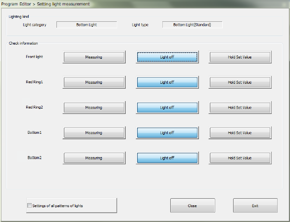
• Light Set
Set the detailed lighting conditions for measurement of the light.
This setting is used to obtain the optimum lighting conditions by setting lighting
individually.
a) Lighting kind
The light category and the light type set in the light data are displayed here.
b) Check information
The list of lights is displayed here.
The buttons <Measuring>, <Light off> and <Hold Set Value> are arranged for each type
of light.
You can select only one of these buttons. The <Measuring> button is enabled by
default.
<Measuring>: Measures the corresponding type of light.
<Light off>:
Turns off the corresponding type of light, and then measures it.
When the system finishes measuring the light normally, the setting for turning off the
light is made in the light data.
<Hold Set
Value>:
Fixes the setting of the light amount of the corresponding type of light to measure the light.
c) Settings of all patterns of lights
When you check off the check box “Setting of all patterns of lights,” the system measures
the light for which the <Measuring> button is set with performing all operations enabled
with the buttons: <Measuring>, <Light off> and <Hold Set Value>.
If the <Light off> button or the <Hold Set Value> button is selected for the light, only the
current setting is enabled without performing the operations described above.
By default, this check box is not checked off.
• Lighting measuring
The optimum lighting conditions for recognizing a component can be automatically
measured.
Part 1 Basic Operation Chapter 4 Creating a Production Program
4-247
5) Result of inspect
An inspection result is displayed. When vision centering is successfully completed, "OK" is
displayed. Otherwise, "NG" is displayed and the cause of the error is displayed in the
"Comment" field.
6) Insp.
Vision recognition inspection is executed. At completion of the inspection, an inspection
result is displayed.
7) Prev. component and Next component
When there is an alternative component, the processing is moved to the alternative
component.
8) OK
After the inspection result is incorporated, the previous screen reappears.
9) Exit
After vision recognition inspection is finished, the previous screen reappears.
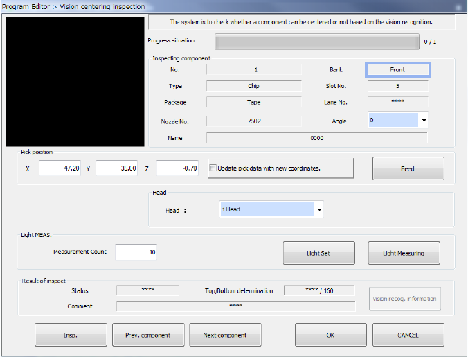
(4) When the side of a square chip component, front or rear, is decided
If you select “The mean value is bright” for the menu item “Inspection algorithm” and execute the
<Insp.> button when the side of a square chip component is decided, the screen changes as
shown below.
1) Result of inspect
The new item for indicating the determination of the component side, front or rear, is
displayed on the screen additionally. “***/threshold value” is displayed by default. When
you execute the inspection, and obtain a measurement value that exceeds the threshold
value, “OK” is displayed instead of “***.”
When the obtained value is equal to or less than the threshold value, “Measurement
result/threshold value” is displayed on the screen.
In this case, the system fails to recognize the component, and the item “Status” shows “NG.”