RS-1_instruction manual.pdf - 第979页
Part 2 D etaile d Descript ion of E ach Functi on Chapter 12 Handling th e Optional Device s 12 - 95 12.14.4 Machine Setup To run a coplanar ity check, you have to make the necess ary settings on the “ Machine Setu p ” s…

Part 2 Detailed Description of Each Function Chapter 12 Handling the Optional Devices
12-94
(4) Measurable range
The measurable range is 1 mm or less. If the area indicated below exceeds 1 mm, an error
occurs.
(5) Retry of measurement
You can set how many times the machine will measure a component again if a measurement
error occurs.
(See Section 8.3.6.8 “Coplanarity.”)
(6) Parameters to be entered for measurement
① Tolerance, which is to determine coplanarity during measurement
② Electrode size: width and length (only for a lead component)
③ Measurement Height Offset
④ Lead Offset
⑤ Exposure Time
(7) Output of measurement results
① Determination if the result is accepted or not as compared to the preset value
② Information on the height of all terminals and determination if the height is accepted or
not
(8) Laser strength
Laser: Class 3B (IEC60825-1:2007), visible radiation
Maximum output: 100 mW
Wavelength: 600 – 700 nm
1mm
Part 2 Detailed Description of Each Function Chapter 12 Handling the Optional Devices
12-95
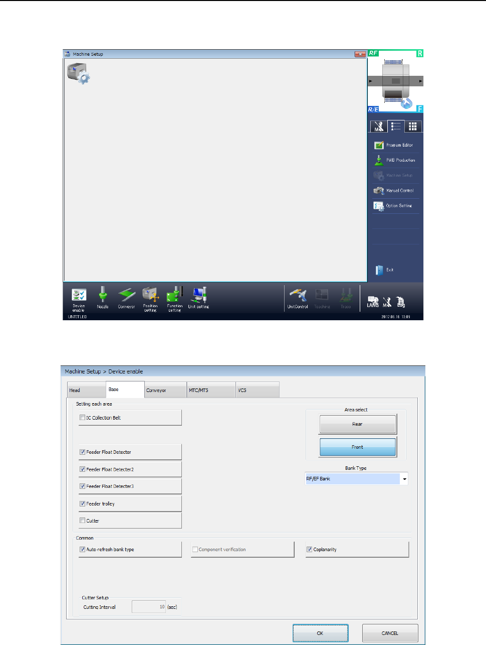
12.14.4 Machine Setup
To run a coplanarity check, you have to make the necessary settings on the “Machine Setup”
screen.
Start up the “Machine Setup” utility.
1) Select the “Device enable” icon from the “Machine Setup” screen menu, and then the “Base”
tab on the displayed screen.
Place a checkmark in the “Coplanarity” check box.
When you place a check mark in this check box, the coplanarity unit is enabled.
Part 2 Detailed Description of Each Function Chapter 12 Handling the Optional Devices
12-96
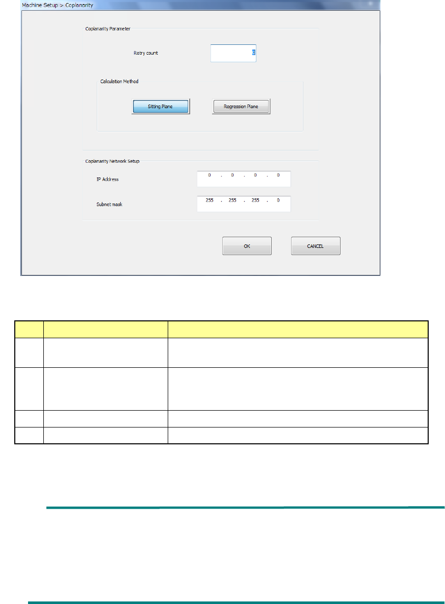
2) Select the “Unit setting” icon from the “Machine Setup” screen menu, and then the
“Coplanarity.”
Specify the menu items “Retry count” and the “Calculation Method.”
No.
Item
Description
1 Retry count Specify how many times to repeat the operation to
obtain coplanarity parameters.
2
Calculation Method
Select the method for calculating the reference plane,
“Sitting Plane” (three-point method) or “Regression
Plane” (least-square method).
3
IP Address
Set the IP address assigned to the coplanarity unit.
4
Subnet mask
Set the subnet mask assigned to the coplanarity unit.
* See Section 8.3.6.8 “Coplanarity” for details
Ball component: Coplanarity is calculated with the least-square
method regardless of the setting of the reference
plane in the “Calculation Method” column.
Unidirectional connector: Only colinearity is calculated with the least-square
method regardless of the setting of the reference
plane in the “Calculation Method” column.