RS-1_instruction manual.pdf - 第230页
Part 1 B asic O peration Chapter 2 Pr oduction 2- 119 1) Component be i ng insp ected The compo nent num ber (“No.”), the bank (“B ank”), the compone nt type (“T ype”) , the attachment hole (“Slot No.”), the component n …
Part 1 Basic Operation Chapter 2 Production
2-118
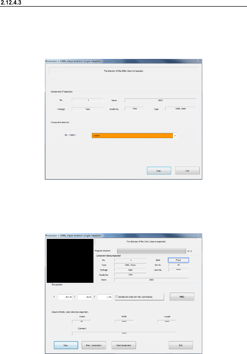
GNRL. Vision direction single inspection
(1) Selecting a component
The data on the component is displayed on the screen. In the combo box of the component
name, general-purpose vision components are displayed as a list. In this list, select a
component to execute inspection.
When you press the <Exit> button, the system returns a nozzle if it is attached on the head, and
then redisplays the previous screen.
When you press the <Insp.> button, the screen shown in the next section appears.
1) “Component of inspection” and “Component selection”
In the combo box of the component name, general-purpose vision components whose
direction is to be checked are displayed as a list. In this list, select a component to execute
inspection.
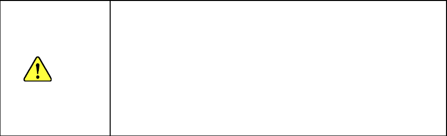
(2) Execution of a check
The OCC moves to the component pick-up position.
Part 1 Basic Operation Chapter 2 Production
2-119
1) Component being inspected
The component number (“No.”), the bank (“Bank”), the component type (“Type”), the
attachment hole (“Slot No.”), the component name (“Name”), the lane (“Lane No.”), the
packaging style (“Package”) and the nozzle number (“Nozzle No.”) are displayed here.
2) Pick position
The coordinates of a component pick-up position are displayed here. If these
coordinates can be taught and the check box “Update pick data with new coordinates” is
checked, the system stores the taught coordinates in the Pick data. If this check box is
not checked, the taught coordinates are applied to the current pick-up operation only.
To teach the X and Y coordinates, align the focus with either the “X” edit box or the “Y”
edit box, and then press the <Teaching> button of the function bar. To teach the Z
coordinate, align the focus with the “Z” edit box, and then press the <Teaching> button
of the function bar.
3) Result of SOT/ GNRL. Vision direction inspection
① SOT direction inspection
The system displays the component size recognized with laser in the “Width” and
“Length” fields. After checking the direction of the SOT component, “OK” or “NG”
appears in the “Status” field according to the check result. If the system fails to
recognize the image of the component, a check error is displayed in the “Status” field.
4) <Insp.> button
The system performs the SOT direction check for the specified component only.
CAUTION
Immediately after you press the <Insp.> button, the head starts moving
and the system starts a check. To avoid injuries, do not put your
hands inside the machine or keep your face or head away from the
machine.
Before pressing the <Insp.> button, check to see if there is no one who
is working the internal parts of the machine.
Before pressing the <Insp.> button, check to see if there is no one who
is near the machine and may be injured.
Before pressing the <Insp.> button, check to see if there is no obstacle
such as an adjustment tool that is located or attached inside the
machine and may prevent the machine from operating normally.
5) <Prev. component> button/<Next component> button
The system changes a component to be inspected to the alternative component.
6) <FEED> button
This button causes a feeder to feed a component.
Part 1 Basic Operation Chapter 2 Production
2-120
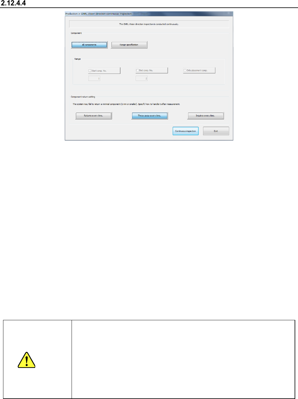
GNRL. Vision direction continuous inspection
(1) Component (to be inspected)
Specify whether to check only components that satisfy a certain requirement(s) among
components whose data is stored in Component data.
1) All components
Among all the component data, SOT components or general-purpose vision components
will be checked..
2) Range of specification
Check this check box if you want to check the components whose numbers are specified
here among the components that satisfy the requirement(s) specified at the “component”
column.
When you check this check box, you can specify the following items.
• Start comp. No.
Enter the number of the first component to be checked here.
The system performs a verify check and changes the value in the “Start comp. No.”
(start component number) edit box.
• End comp. No.
Enter the number of the last component to be checked here.
The system performs a verify check and changes the value in the “End comp. No.”
(end component number) edit box.
• Only placement comp.
Check this check box if you want to check only components whose data is stored in
Placement data also.
CAUTION
Immediately a
fter you press the<Continuous inspection>button, the head
starts moving and the system starts inspection.
To avoid injuries, do not put your hands inside the machine or keep your face
or head away from the machine.
Before pressing the <Continuous inspection> button, check to see if there is no
one who is working the internal parts of the machine.
Before pressing the <Continuous inspection> button, check to see if there is no
one who is near the machine and may be injured.
Before pressing the <Continuous inspection> button, check to see if there is no
obstacle such as an adjustment tool that is located or attached inside the
machine and may prevent the
machine from operating normally.
(2) Component return setting
Select how to handle a minimal component after checking it.
1) Throw away every time
The system discards a component according to the setting of the menu item “Compo Reject