RS-1_instruction manual.pdf - 第366页
Part 1 B asic O peration Chapter 4 Cr eating a Produc tion Progra m 4- 31 4.3.3 .6 PWB Conveyor This tab allo ws you to ma ke the detailed settin gs of the conv eyor and t he support t able. The “ PWB Conv eyor ” scr een…
Part 1 Basic Operation Chapter 4 Creating a Production Program
4-30
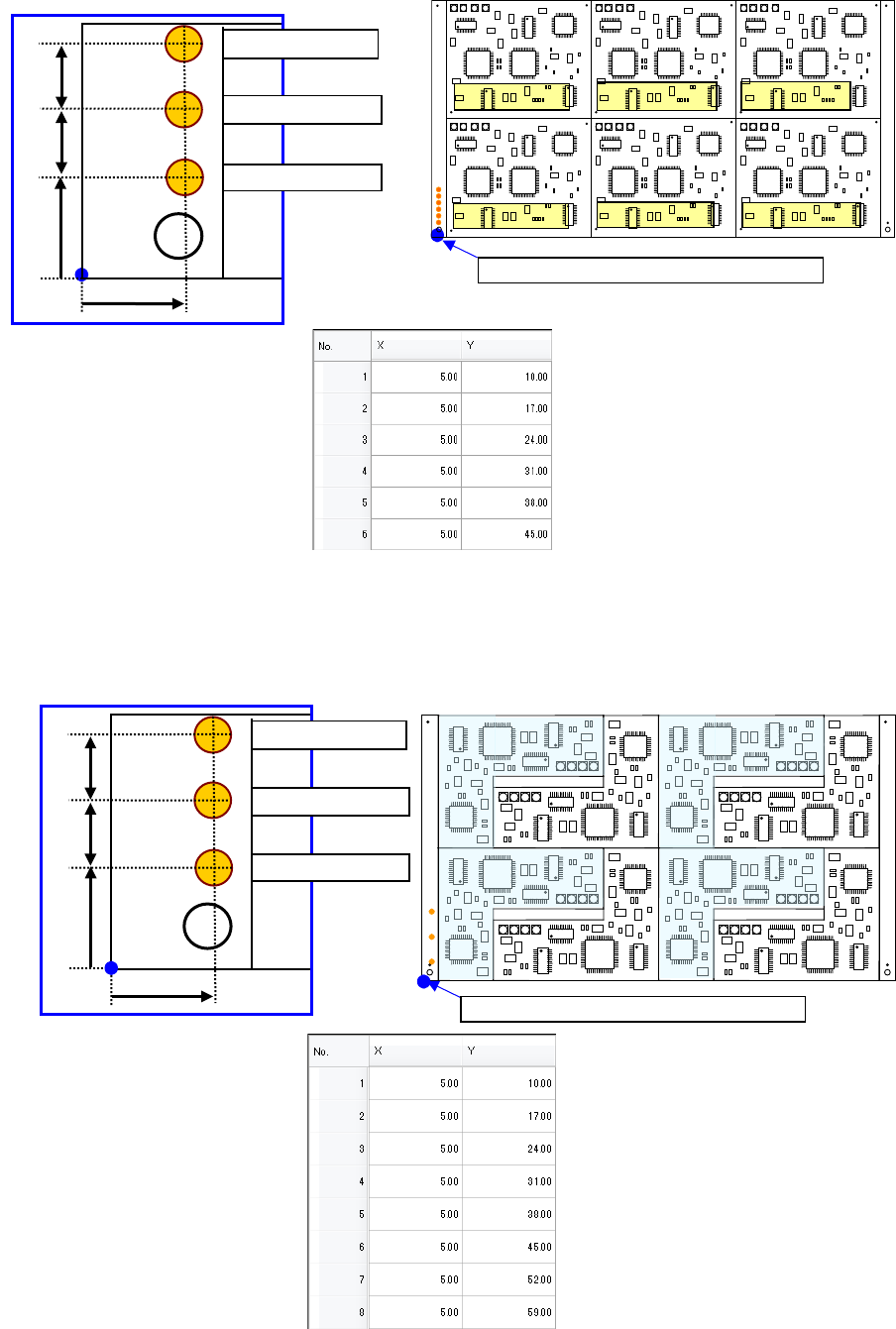
♦ Multi-circuit matrix
The order of circuits is the X-direction pitch/Y-direction pitch from the reference circuit.
♦ Multi-circuit non-matrix
The order of circuits set by circuit arrangement is used.
Circuit No.4
PWB position reference [PWB origin]
Circuit No.1
Circuit No.2
Circuit No.3
Circuit No.5
Circuit No.6
For circuit No.1
For circuit No.3
10mm
7mm
For circuit No.3
5mm
7mm
PWB position reference [PWB origin]
For circuit No.1
For circuit No.3
10mm
7mm
For circuit No.2
7mm
5mm
Part 1 Basic Operation Chapter 4 Creating a Production Program
4-31
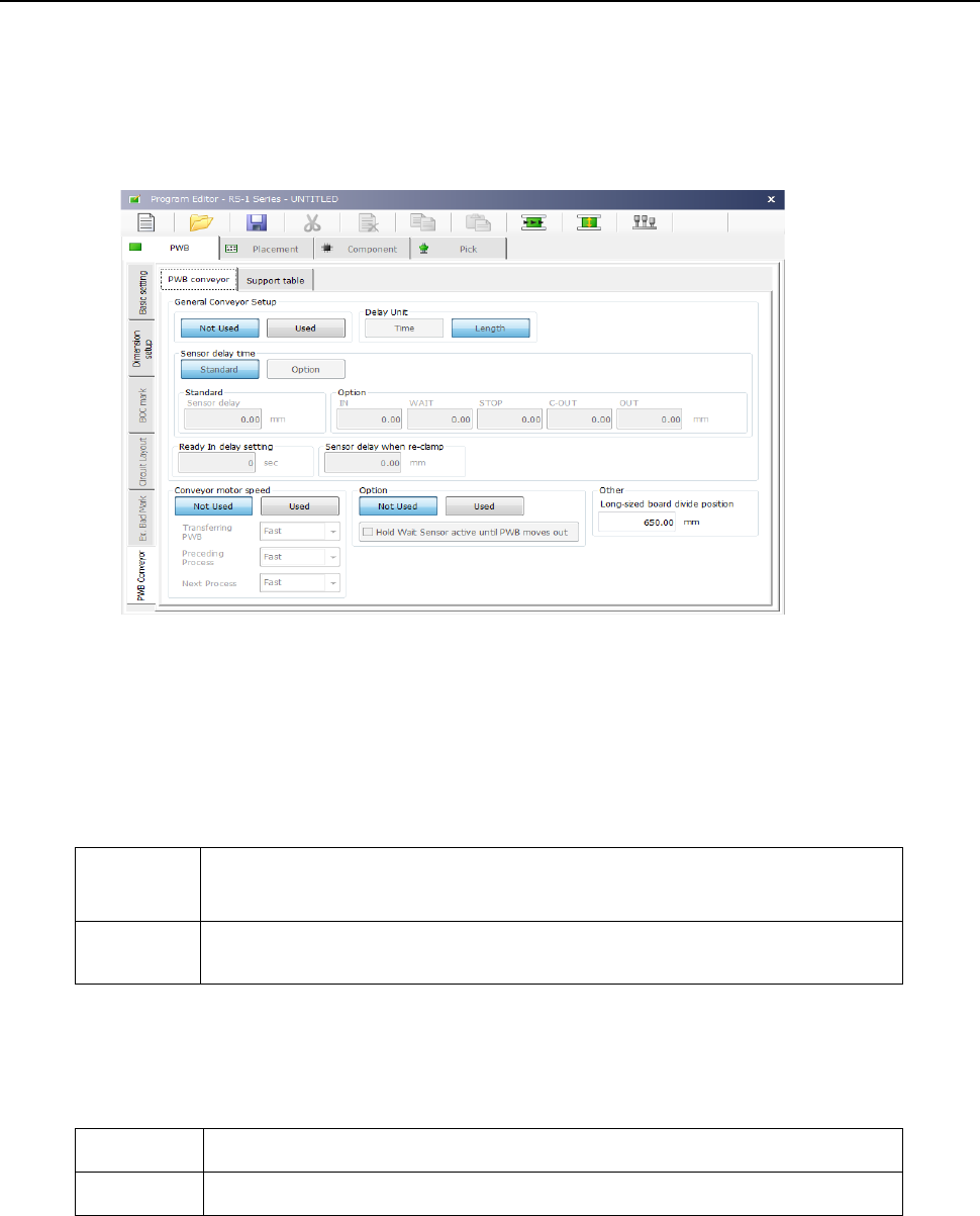
4.3.3.6 PWB Conveyor
This tab allows you to make the detailed settings of the conveyor and the support table.
The “PWB Conveyor” screen consists of the “PWB conveyor” tab and the “Support table” tab.
(1) “PWB conveyor” tab
When you select the “PWB Conveyor” tab located at the lower left corner of each “PWB” data
screen, the following screen appears.
The “PWB conveyor” tab consists of the “General Conveyor Setup” group, the “Conveyor motor
speed” group, the “Option” group and the “Other” group.
1) “General Conveyor Setup” group
① Not Used/Used
Select whether to use the data set in the “General Conveyor Setup” group or not.
Not Used
Select this button when you do not use the data in the “General Conveyor
Setup” group.
The system operates according to the settings of the main unit.
Used
Select this button when you use the data in the “General Conveyor Setup”
group.
② Delay Unit
Select the unit for the delay time of the conveyor sensor, “Time” (ms: 1/1000 second) or
“Length” (mm).
Time Select this button to set the unit of the delay time to 1/1000 second (ms).
Length Select this button to set the unit of the delay time to mm.

Part 1 Basic Operation Chapter 4 Creating a Production Program
4-32
③ Sensor delay time
Select whether to set the delay time of each sensor to the same value or not.
Standard Select this button to set the delay time of each sensor to the same value.
Option Select this button to set the delay time of each sensor respectively.
When you select the <Standard> button, the value set in the “Sensor delay” field under the
title “Standard” becomes active. When you select the <Option> button, the delay time set
in the field for each sensor under the title “Option” becomes active.
④ Standard
When you select the “Standard” radio button in the “Sensor delay time” field, set the delay
time or delay length.
The allowable range for each unit is 0 to 2,500 (ms) and 0 to 1,000 (mm).
⑤ Option
When you select the “Option” radio button in the “Sensor delay time” field, set the delay time
or delay length of each of the sensors: the IN sensor, the WAIT sensor, the STOP sensor,
the C-OUT sensor and the OUT sensor.
The allowable range for each unit is 0 to 2,500 (ms) and 0 to 1,000 (mm).
⑥ Ready In delay setting
Normally, when the Ready IN signal (signal for receiving the ejected board to be input from
the post process) is set to ON, the system passes the board to the post process without
stopping the board.
However, when you set this delay time here, the system stops transportation of a board
when the OUT sensor detects it, and then the system rotates the motor again to eject the
board when the Read IN signal is set to ON after the specified time passes. This delay
time is useful for passing/receiving a board between the machines whose board transporting
speeds are different from each other. Note that this delay time starts counting when the
OUT sensor is set to ON.
⑦ Sensor delay when re-clamp
Set a period of delay time or a length when the PWB is not removed and is re-clamped at
the production restart after the production has been completed due to production failure
such as feeder float-up, etc.
Set a value ranging from 0 to 5000 (ms) or 0 to 200 (mm).
2) “Conveyor motor speed” group is explained below.
① Not Used/Used
Select whether to use the settings made in the “Conveyor motor speed” group or not.
Not Used
Select this button if you do not use the settings made in the “Conveyor
motor speed” group.
The motor is operated based on made with the main unit side.
Used
Select this button if you are to use the settings made with the “Conveyor
motor speed” group.
② Transferring PWB
Set the transport speed to carry the PWB to the center buffer.
③ Preceding Process
Set the speed in which the machine loads a board from the previous process until it finishes
loading the board into it completely (until the IN sensor is set to OFF).
④ Next Process
Set the speed for transporting a board on which components are placed to eject it to the
post process.