RS-1_instruction manual.pdf - 第578页
Part 1 B asic O peration Chapter 4 Cr eating a Produc tion Progra m 4- 243 2) Placement pos ition Menu item Overvi ew Circuit no Circuit being mea sured/To tal number of circuits An gle C omponent place m ent angle being…
Part 1 Basic Operation Chapter 4 Creating a Production Program
4-242
(2) Executing measurement of the height of a PWB on which components are placed
Immediately after you press the <EXEC> button, the system performs BOC alignment operation
before measurement if BOC marks are set in a production program. (The system recognizes
BOC marks on all circuits.)
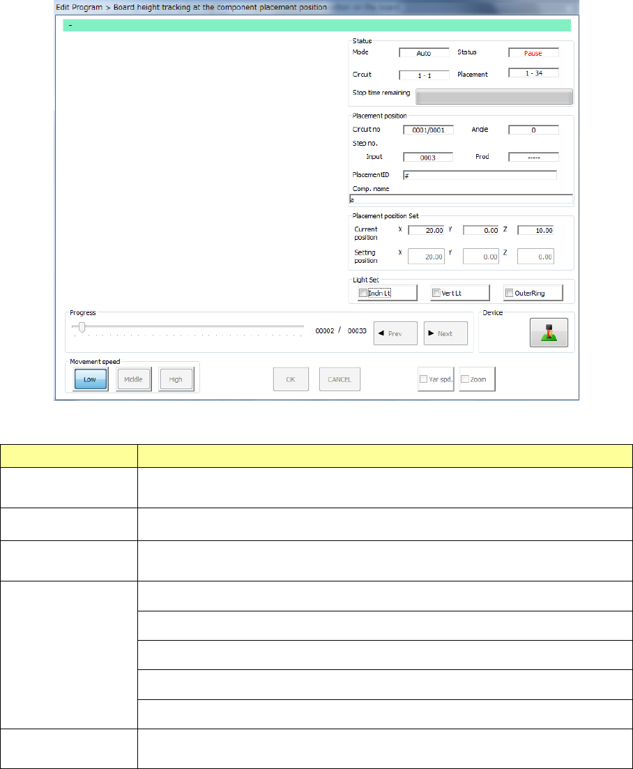
While the system is measuring the height of a PWB on which components are placed, the
following screen appears.
1) Status
Menu item Overview
Mode
The feeding method specified with the menu item “Feed method,” “Auto” or
“Manual,” is displayed here.
Circuit The range of circuits whose heights are to be measured is displayed here.
Placement
The range of component placement positions at which the height is to be
measured is displayed here.
Status
“Moving” indicates that the axis is moving.
“Pause” indicates that the axis stops temporarily in Automatic Feed mode.
“Stop” indicates that the axis stops manually or intentionally.
“Axis esc” indicates that the axis is moving to the safety position.
“Mark recog” indicates that the system is recognizing an IC mark.
Stop time
remaining
The progress bar shows the remaining stop time in Automatic Feed mode.
Part 1 Basic Operation Chapter 4 Creating a Production Program
4-243
2) Placement position
Menu item Overview
Circuit no Circuit being measured/Total number of circuits
Angle Component placement angle being measured
Step no. Placement data number being measured
Placement ID Placement ID being measured
Comp. name Name of a component being measured
3) Placement position set
The current measured coordinates are displayed in the “Current position” fields, while the
coordinates set on the “Placement” data screen are displayed in the “Setting position” fields.
4) Light Set
Select OCC lighting that is used to display the placement point.
5) Progress
When you move this slider as desired while the system stops, it can move the tracking
position to the previous placement position or the next one.
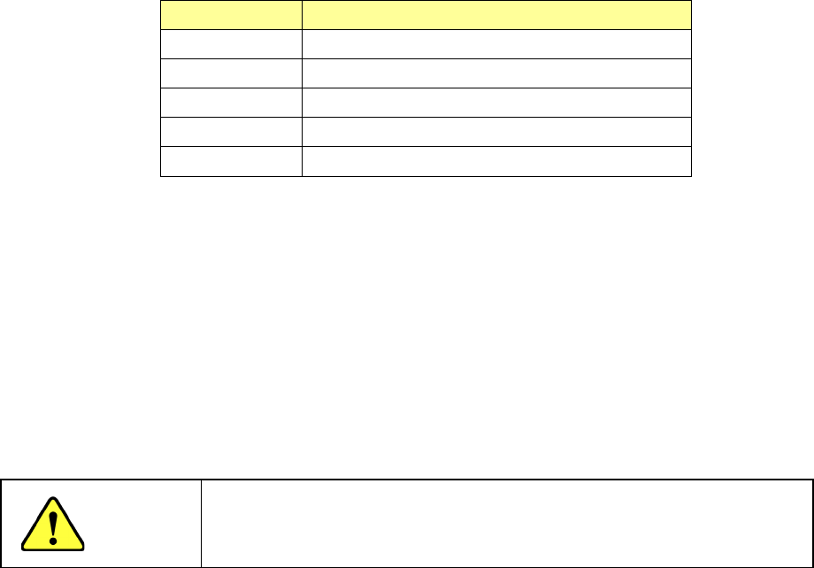
CAUTION
To avoid a risk of injury, do not put your hands inside the machine nor
move your face or head close the machine while you are operating the
machine.
Part 1 Basic Operation Chapter 4 Creating a Production Program
4-244
4.5.7.3 Recognize
This command attaches an actual component on a head to check to see if the component can be
centered with a VCS.
(1) Inspection method for vision recognition inspection
A series of vision centering operation is controlled based on the values set in the Component data
to check to see if any error does not occur.
(2) Various operations at vision recognition inspection
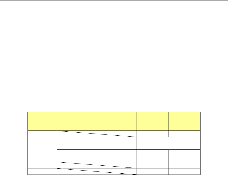
1) Return of component after inspection
After a component is checked, it may be returned to its original position or discarded
depending on its packaging style as shown in the table below.
Where to discard a component is determined according to the setting of the menu item
“Component reject to.”
Since a component whose size is 1 mm or less may be placed on its side or turned upside
down when it is returned, the system displays the message so that you can select how to
handle it.
Packaging
style
Condition 2
Returning a
component
Discarding
a
component
Tepe
―
○
The shorter side length of the
outer dimensions is 1 mm or less.
Query * 1
The shorter side length of the
outer dimensions is 1 mm or more.
○ ―
Tray
○
―
Stick
―
○
*1 The system displays the dialog box on which you have to select whether to return a
component or discard it. The system displays this dialog box before it starts continuous
measurement of components in Continuous Measurement mode.
2) Selecting a component supply unit
If two or more component supply units are assigned to the same type of component in Pick
data, a component starts being picked up based on the data you entered first by default.
You can change a component supply unit intentionally also.
3) Changing the coordinates of a component pick-up position
If the system cannot pick up a component normally, you can manually enter a component
pick-up position or teach the coordinates of the pick-up position to change it.
4) Manual pick-up of a component
If there is no Pick data created, you can manually attach a component to the nozzle. In this
case, you cannot enter any pick-up coordinates. You cannot operate a feeder either.
When you pick up a component manually, the system cannot discard it if its shorter side
length exceeds 33.5 mm. Therefore, the component is moved to the protection position
after measurement.