RS-1_instruction manual.pdf - 第440页
Part 1 B asic O peration Chapter 4 Cr eating a Produc tion Progra m 4- 105 The “V ision 2” tab a llo ws y ou to set inf ormat ion on leads. Menu item Overvie w Length Enter the lengt h of a sect ion of a lead t hat is in…
Part 1 Basic Operation Chapter 4 Creating a Production Program
4-104
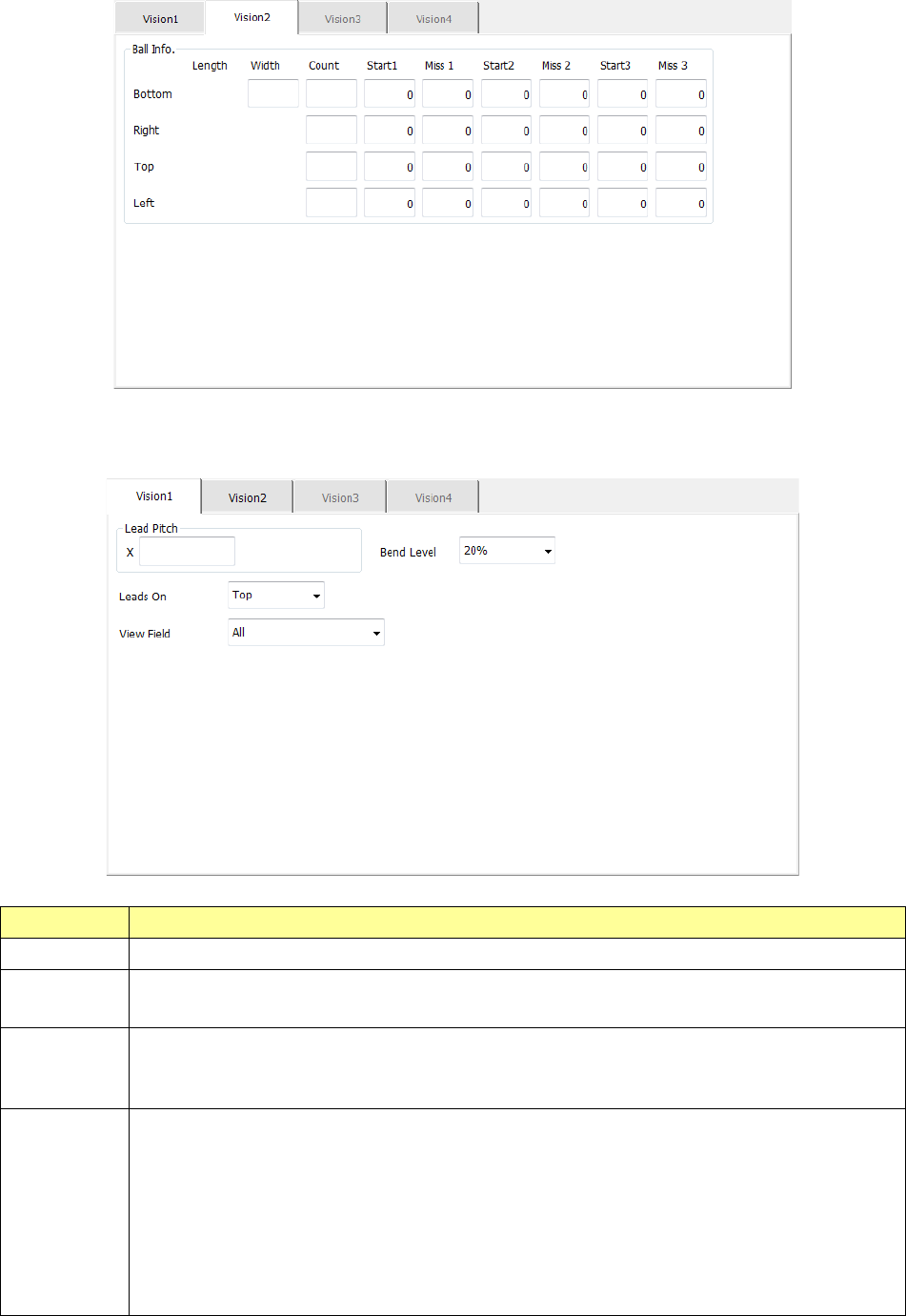
The “Vision 2” tab allows you to set information on balls.
8) Unidirectional lead
The “Vision 1” tab allows you to set the lead pitch and the lead bending level.
Menu item Overview
Lead Pitch Enter the distance between two consecutive leads.
Bend level
Select the bending level of a lead to be detected among “15 %,” “20 %,” “25 %,” “30 %” and “None.”
The default value is 20 %.
Leads On
Select the lead direction, “Top” or “Bottom.”
The items displayed in the “View Field” and the input section of the “Lead info.” column displayed
on the “Vision 2” tab are switched according to this setting.
View Field
Select the range of leads of a connector component to be recognized and that not to be recognized
among “All” (all leads), “Only the both ends lead” (only leads on both ends) and “Both ends lead
exclusion” (leads on both ends are excluded).
“All” is selected by default.
When you select “Only the both ends lead” or “Both ends lead exclusion”:
- If “Top” is selected for the menu item “Leads On,” the items “L Top” and “R Top” are displayed.
- If “Bottom” is selected for the menu item “Leads On,” the items “L Bot.” and “R Bot.” are
displayed.
Part 1 Basic Operation Chapter 4 Creating a Production Program
4-105
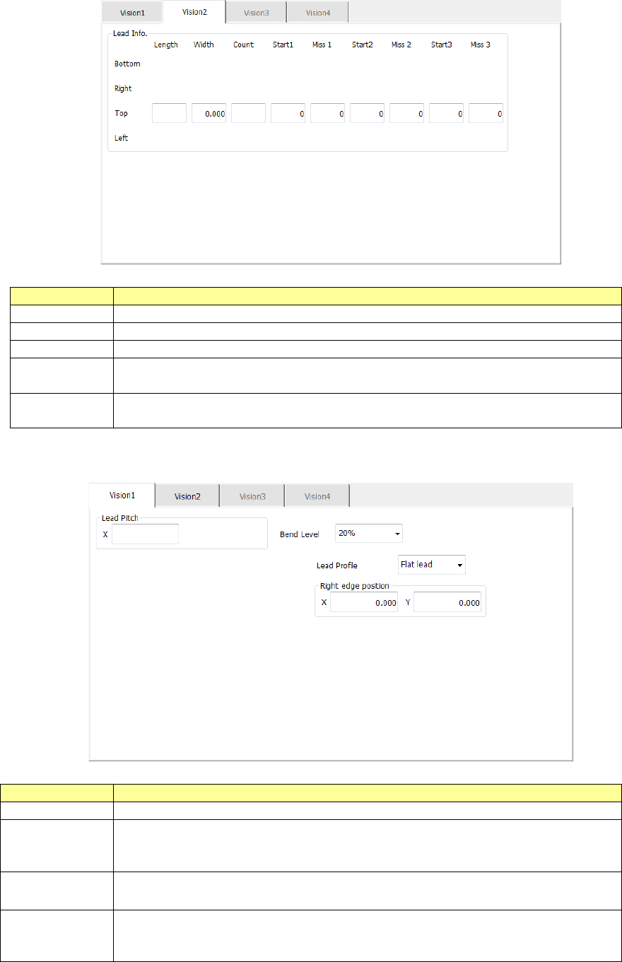
The “Vision 2” tab allows you to set information on leads.
Menu item
Overview
Length
Enter the length of a section of a lead that is in contact with a board.
Width
Enter the width of a lead.
Count
Enter the number of leads when a component type is a lead component.
Start 1 to 3
Enter the position of a missing lead.
The input range is from 0 to the number of leads (default: 0).
Miss 1 to 3
Enter the number of missing leads.
The input range is from 0 to the number of leads (default: 0).
9) Extended lead
The “Vision 1” tab allows you to set the lead pitch and the lead bending level.
Menu item
Overview
Lead Pitch
Enter the distance between two consecutive leads.
Bend level
Select the bending level of a lead to be detected among “15 %,” “20 %,”
“25 %,” “30 %” and “None.”
The default value is 20 %.
Lead Profile Select the lead shape, “Flat lead” or “Gullwing lead.”
Right edge
position
Enter the position of the right edge of a lead in the “X” and “Y” fields.
Input range of the “X” field: - 99.00 to 99.00
Input range of the “Y” field: - 99.00 to 99.00
Part 1 Basic Operation Chapter 4 Creating a Production Program
4-106
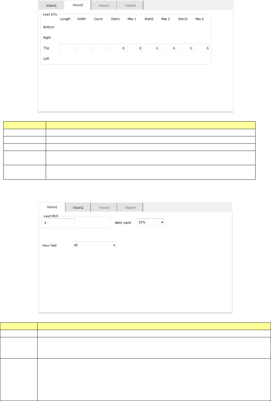
The “Vision 2” tab allows you to set information on leads.
Menu item
Overview
Length
Enter the length of a section of a lead that is in contact with a board.
Width
Enter the width of a lead.
Count
Enter the number of leads when a component type is a lead component.
Start 1 to 3
Enter the position of a missing lead.
The input range is from 0 to the number of leads (default: 0).
Miss 1 to 3
Enter the number of missing leads.
The input range is from 0 to the number of leads (default: 0).
10) Bidirectional lead, Z-lead
The “Vision 1” tab allows you to set a lead pitch and a lead bending level.
Menu item
Overview
Lead Pitch
Enter the distance between two consecutive leads.
Bend level
Select the bending level of a lead to be detected among “15 %,” “20 %,” “25 %,”
“30 %” and “None.”
The default value is 20 %.
View Field
Select the range of leads of a connector component to be recognized and that not to
be recognized among “All” (all leads), “Only the both ends lead” (only leads on both
ends) and “Both ends lead exclusion” (leads on both ends are excluded).
“All” is selected by default.
When you select “Only the both ends lead” or “Both ends lead exclusion,” the items
“L Top,” “R Top,” “L Bot.” and “R Bot.” are displayed.