RS-1_instruction manual.pdf - 第173页
Part 1 B asic O peration Chapter 2 Pr oduction 2- 62 1) Image view Using images, t he upper half portion of the “Electric f eeder check” s creen shows t he condi tion of the feeder us ed for t he current prod uction prog…
Part 1 Basic Operation Chapter 2 Production
2-61
2.10 Electric feeder check
In the electric feeder check, the system checks whether or not correct components are put on the
electric feeder set for the current production program and displays the check results.
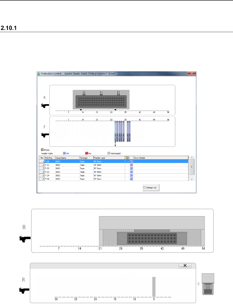
“Electric feeder check” screen
(1) “Electric feeder check” menu
Click the [Window] menu command on the “Product” menu and select the [Electric feeder
check].
(2) Contents
When a TR8SR is used as a component supply device, the TR8SR image is displayed on the
screen as shown below.
When you touch the displayed TR8SR image, the enlarged TR8SR image is displayed.
To return to the original TR8SR image screen, touch “×” or the TR8SR image displayed on the
right side of the screen.
Part 1 Basic Operation Chapter 2 Production
2-62
1) Image view
Using images, the upper half portion of the “Electric feeder check” screen shows the condition
of the feeder used for the current production program.
(Note: A feeder with the skip designation or actually not used for the production as specified
in the production conditions is not displayed on the image view.)
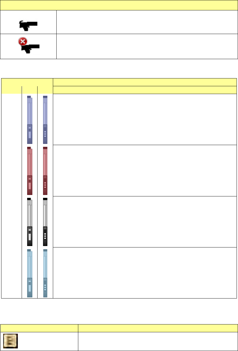
The bank type is displayed as shown in the table below.
Bank status
The production bank matches the connected bank.
The production bank does not match the connected bank.
* If the program does not match the bank, you cannot start production.
Electric feeder-setting mistake conditions are shown in different colors.
Feeder color
Description
EF
RF
Blue
Electric feeder is mounted that all of the component, feeder type, feed pitch,
and other items are correct.
Red
Electric feeder, in which an error occurs, is mounted.
Review the component, feeder type, or feed pitch, etc.
Additionally, if the bank is different from that in the production program or
setup, or mounted actually, the feeder is shown in red.
Gray
Electric feeder, which is set in the production program, but not loaded (i.e. not
connected), is mounted.
Light
blue
A feeder selected on the list is mounted.
When you click the feeder image displayed on the screen to select it, the
corresponding feeder is selected on the list also.
Additionally, if the component run-out condition is notified, the icon is overlap-displayed
on relevant feeder.
Icon
Description
:Component run-out
This icon is overlap-displayed on the feeder, in which the
component run-out occurs.
Part 1 Basic Operation Chapter 2 Production
2-63
2) List
Using lists, the lower half portion of the “Electric feeder check” screen shows the condition of
the feeder used for the current production program.
(Note: A feeder with the skip designation or actually not used for the production as specified
in the production conditions is not displayed in the list.)
No.
Item
Contents
1
No.
Shows the feeder No.
2
Pick Pos.
Shows the pickup position in the format “Bank-Hole position: Lane
No.”.
The lane No. is not shown if the lane display is not needed.
3
Comp Name
Shows the component name specified in the production program.
4
Package
Shows the feeder package specified in the production program.
5
Feeder type
Shows the feeder type specified in the production program.
Each feeder type is displayed as follows.
Electric feeder: E xxxx,
Electric feeder (RF): RF xxxx,
Electric Stick feeder: E Stick xxxx,
6
Component run-out
mark
: Shown if the component run-out occurs.
7
Icons for showing an
Electric feeder
mounting mistake
check
Shows the electric feeder-setting mistake status.
: Electric feeder OK
: Electric feeder NG
: Electric feeder unloaded
8
Error Details
Shows error details if the electric feeder-setting mistake occurs.
For details, see the list of error details shown below.