RS-1_instruction manual.pdf - 第151页
Part 1 B asic O peration Chapter 2 Pr oduction 2- 40 CAUTION Immediatel y after you pres s the <S TART> sw itch, the h ead starts mo ving and the system starts prod uction. To avoid inj uries, do not pu t your han …
Part 1 Basic Operation Chapter 2 Production
2-39
Start of production
Specify the production requirements, and then press the <START> switch on the operation panel.
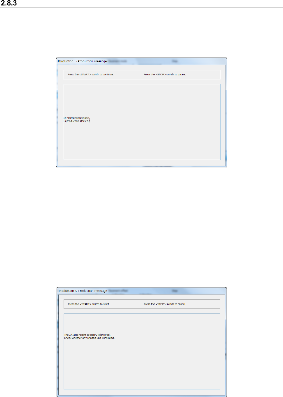
When the <Maintenance Key> is set to Maintenance mode, the following screen appears. Set the
<Maintenance Key> to Production mode, and then press the <START> switch on the operation
panel. If you do not want to start PWB production, press the < STOP> switch on the operation
panel.
When you press the <START> button to start PWB production, one of the following screens
appears according to the previous setting: “Production status (Production condition)” screen (see
Section 2.8.3.1 “Production condition”), “Production status (Vision)” screen (see Section 2.8.3.2
“Vision”), “Production status (Operation condition)” screen (see Section 2.8.3.3 “Operation
condition”), and “Production status (Number of produced PWBs)” screen (see Section 2.8.3.4
“Number of produced PWBs”).
If the system has never performed the origin return operation before you press the
< START > switch, press the < START > switch at first to return each device to its home position,
and then press the < START > switch again.
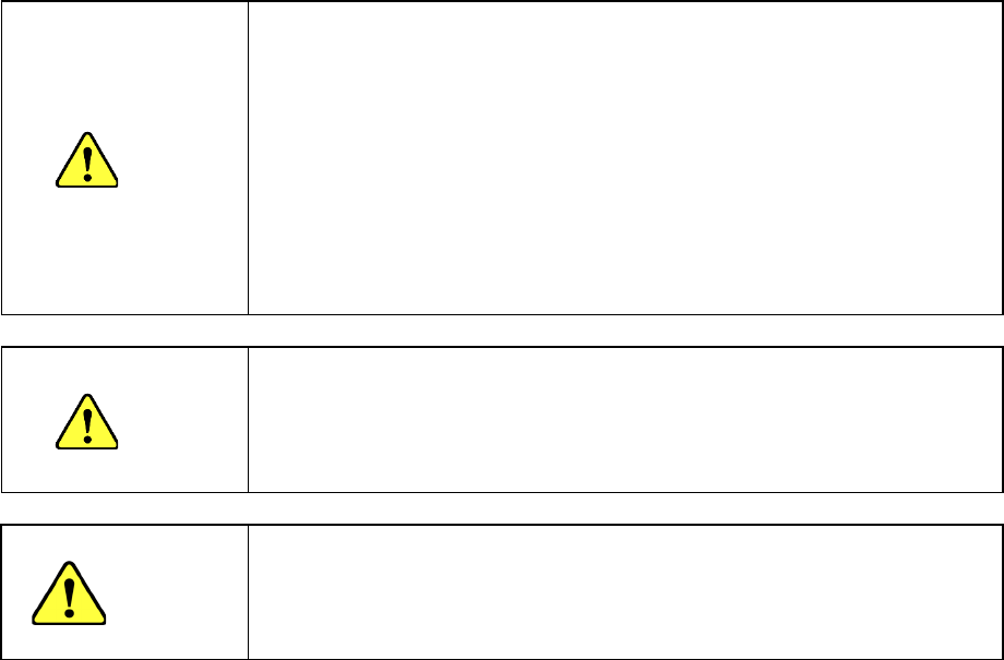
When the ZA-axis operates at a 3mm-height at the production start, the following notice message
will appear. Carefully check that there is no unused unit that interferes with the head, and then press
the <START> switch again.
Part 1 Basic Operation Chapter 2 Production
2-40
CAUTION
Immediately after you press the <START> switch, the head starts moving and the
system starts production.
To avoid injuries, do not put your hands inside the machine or keep your face or
head away from the machine.
Before pressing the <START> switch, check to see if there is no one who is
working the internal parts of the machine.
Before pressing the <START> switch, check to see if there is no one who is near
the machine and may be injured.
Before pressing the <START> switch, check to see if there is no obstacle such as
an adjustment tool that is located or attached inside the machine and may prevent
the machine from operating normally.
When the ZA-axis operates at a low height, carefully check that the head unit does
not interfere with any unused unit.
CAUTION
If the system has never recognized the feeder bank (for example, immediately after
each device of the machine returned to its home position or after the bank moved
down, then up), the system automatically tries to recognize the feeder bank before
moving to the component pick-up position. While the system is recognizing the
feeder bank, the head moves across the feeder. Do not move your hands or face
close the machine.
CAUTION
Note on use of the IFS-NX
Only after checking the component collation state, press the <START> switch.
If a component is not collated yet, or if the collation result has any problem, you
cannot start PWB production with the machine. Refer to the “IFS-NX Instruction
Manual” for details.
Part 1 Basic Operation Chapter 2 Production
2-41
Production condition
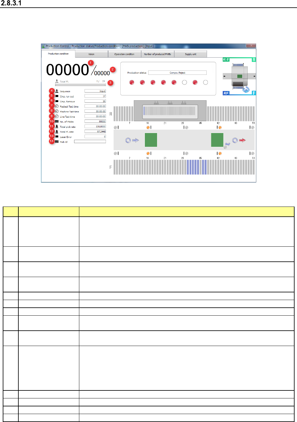
When you select the [Window] command, and then the [Production status (Production condition)]
command, the “Production status (Production condition)” screen appears. This screen shows the
state of each device during PWB production.
- “Production condition” screen
1) Items for production information
The general information on PWB production is displayed here.
No. Item Description
1
Number of PWBs
already produced
Shows the number of PWBs that have been already produced here.
When the item “Count down the number of boards produced” is selected on the
“Production (Display)” tab of the “Operation option” menu, this field shows “the number
of PWBs that will be produced from now.”
2
Planned number of
PWBs to be produced
Shows the number of PWBs planned to be produced here.
3 Total Pl.
Shows the number of components already placed and the total number of
components to be placed on boards.
4 Sequence
Shows the component placement sequence being currently performed (Input order or
Optimized order).
5
Cmp. run out
Shows the accumulated number of times components run out.
6
Cmp. Remove
Shows the accumulated number of times a picked-up component was discarded.
7
Fastest Tact time
Shows the shortest cycle time of the machine. (Shortest placement time)
8 Machine Tact time
Shows the time passed from when one board was loaded to the machine until when
the board was ejected from the machine.
9 Line Tact time
Sows the time passed from when one board was ejected from the machine until when
the next board was ejected.
10 No. of PWBs
Shows “the number of PWBs produced already / the number of PWBs planned to be
produced.”
When the item “Count down the number of boards produced” is selected on the
“Production (Display)” tab of the “Operation option” menu, this field shows “the number
of PWBs that will be produced from now / the number of PWBs planned to be
produced.”
11
Total pick rate (%)
Shows the total component pick-up rate of the machine.
12
Total Pl. rate (%)
Shows the total component placement rate of the machine.
13
Laser Error
Shows the accumulated number of times a laser recognition error occurred.
14
Pwb ID
Shows a PWB ID of a production program.