RS-1_instruction manual.pdf - 第26页
Part 1 B asic O peration Chapter 1 Overv iew of the Machine 1-8 ① ② ⑦ ③ ⑤ ⑧ ⑥ ④ ⑤ ⑨ ⑫ ⑩ ⑪ ⑩ Configuration of the mac hine ① Front liquid cryst al m onitor ⑤ Mini sig nal light (option) ⑨ Rear l iquid crystal mo nitor ② O…

Part 1 Basic Operation Chapter 1 Overview of the Machine
1-7
Other supplied devices
IC collection belt
△
Linear type transcription unit
(To be installed on the main unit / front or rear)
-
Linear type transcription unit
(To be attached on an electric bank/front or rear)
-
Rotary type transcription unit
(To be attached on a bank/front or rear)
-
Feeder setup stand for electric feeder (EF)
△
Feeder setup stand for electric feeder (RF)
△
RF_ETF_Attachment,
△
Descriptions of the abbreviations used in this Manual
Abbreviation Meaning
ATC
(Auto Tool Changer)
CVS
(Component Verification System)
DTS
(Dual Tray Server)
ETF
(Electric Tape Feeder)
HMS (Height Measurement System)
IFS-NX
(Intelligent Feeder System)
LNC
(Laser align New Concept)
MTC
(Matrix Tray Changer)
MTS
(Matrix Tray Server)
OCC
(Offset Correction Camera)
PWB
(Printed Wiring Board)
S-VCS
(Scanning Vision Centering System)
VCS
(Vision Centering System)
Part 1 Basic Operation Chapter 1 Overview of the Machine
1-8
①
②
⑦
③
⑤
⑧
⑥
④
⑤
⑨
⑫
⑩
⑪
⑩
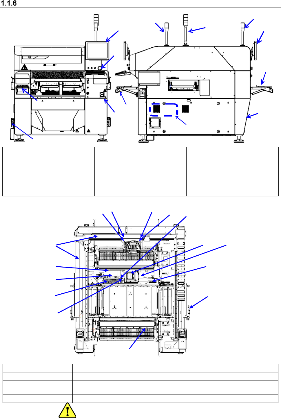
Configuration of the machine
① Front liquid crystal monitor ⑤ Mini signal light (option) ⑨ Rear liquid crystal monitor
② Operation panel ⑥ Air regulator (Under the cover)
⑩
Front tape setting unit
* In and after Rev. D
③ Power switch
⑦
Vacuum pump
(Right side inside the machine)
⑪
Rear tape setting unit (Option)
* In and after Rev. D
④ Signal light
⑧
Breaker
(On the right side of the rear)
⑫ Keyboard (option)
①
ATC unit
⑤
PWB transport unit
⑨
CAL block unit
⑬
Load control unit (option)
②
LNC120 head unit
⑥
VCS unit
⑩
Feeder bank unit
⑭ Coplanarity unit (option)
③
Head unit
8-head
⑦ X-Y unit ⑪ HMS unit
⑮
NozzleRFID reader
(option)
④
OCC unit (L)
⑧
CVS unit (option)
⑫
Trash box
③
①
②
⑥
⑦
⑨
④
⑩
⑪
⑫
⑬
⑤
⑧
⑭
⑮
Part 1 Basic Operation Chapter 1 Overview of the Machine
1-9
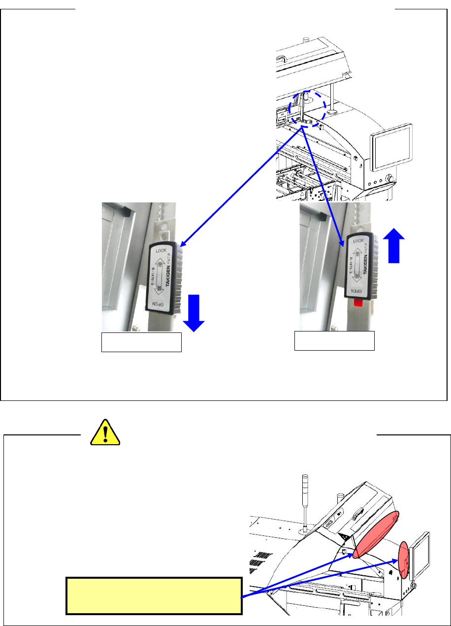
♦ To open the cover, push up the cover and push
the lock lever in the direction of the arrow
(LOCK) for locking.
Release it after confirming the locked status.
* If the cover is released in a non-locked status,
it may fall.
♦ When closing the cover, release the locked status
and then close the cover. Raise the cover and pull
the lock lever in the OPEN direction to release the
lock status.
(During a release operation, take care not to get hurt due to falling of the cover.)
* Do not apply an excessive load to the cover, handle, etc.
♦ When you service the ATC, the XY-axes or
the head, or when you enter the machine to
operate its inside, be extremely careful not to
bump into the cover or the monitor from the
rear side or hit your head on any part to avoid
injury.
<Precaution for operation inside the machine>
<Precautions for opening/closing the safety cover>
Be careful not to hit your head
or other part on these parts.
OPEN
LOCK