RS-1_instruction manual.pdf - 第828页
Pa r t 2 Det ai l ed Des c r i pti on o f Ea c h Fu nc ti on Chapter 10 M ach i ne Manage m e nt Infor m ation 10 - 15 3) <R eset> but ton This b utt on i s des cr ib ed in t he sub - sec tion l at er. (2) Scr een …
Part 2 Detailed Description of Each Function Chapter 10 Machine Management Information
10-14
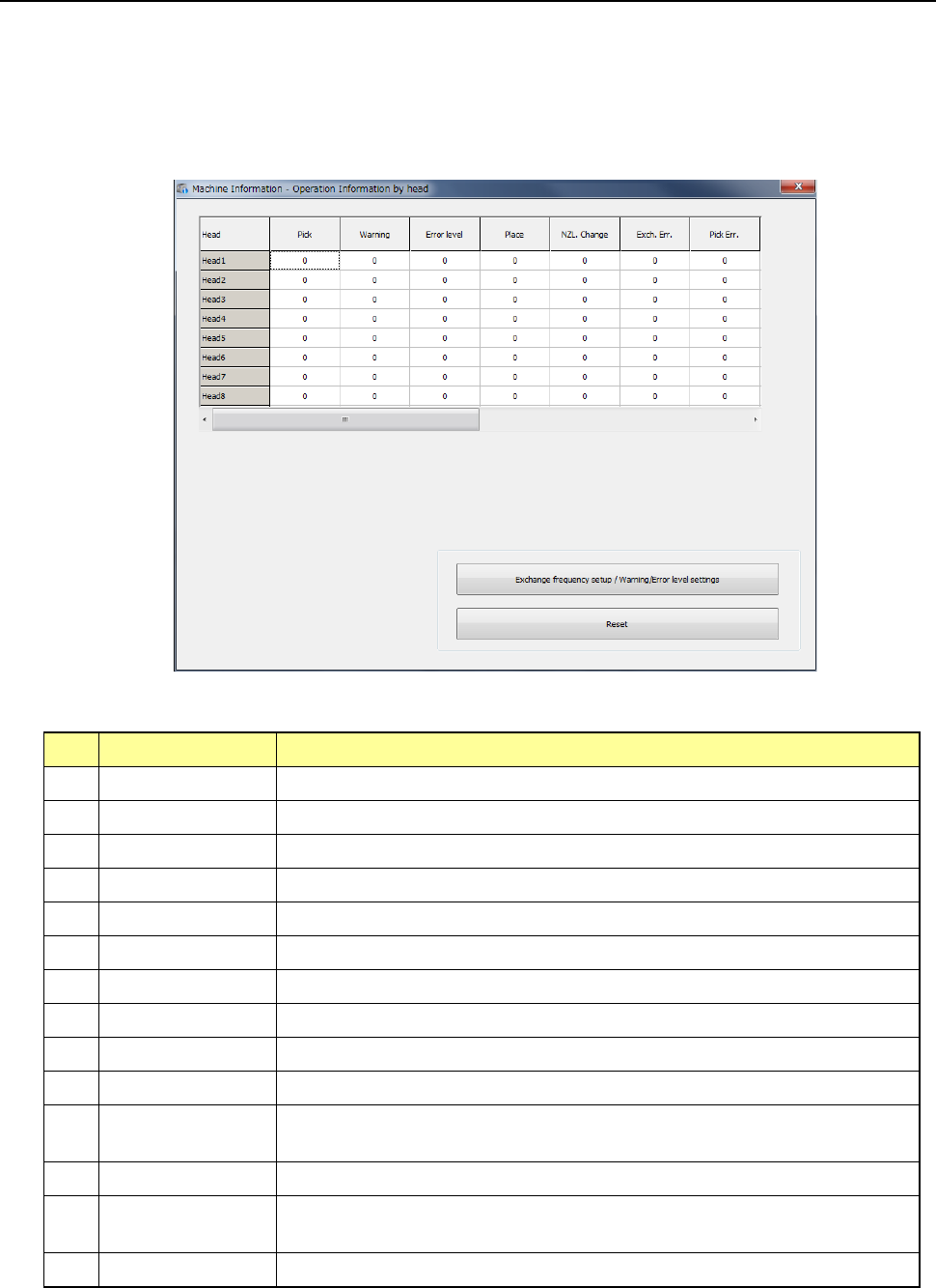
10.3.5 Operation Information of each head
This command displays the operation information on each head.
(1) Displayed screen
When you select [Machine] – [Operation information by head] in the main menu, the
“Operation Information by head” screen appears.
This screen is changed over to the information by bank by pressing <Select device> button.
1) List
The number of operations of each head and the related data are displayed in the list.
No. Item Description
1 Pick Counts how many times the nozzle picked a component totally.
2 Warning Displays the warning level.
3 Error level Displays the error level.
4 Place Counts how many times the nozzle placed a component successfully.
5 NZL Change Counts how many times the nozzle was replaced successfully.
6 Exch. Err. Counts how many times a replacement error occurred per a nozzle.
7 Pick Err. Counts how many times a pick-up error occurred per a nozzle.
8 Retry Counts how many times a component pick-up retry over error occurred.
9 LA Recog Counts how many times a laser recognition error occurred.
10 Chip Counts how many times a chip rise error occurred.
11 Dimension Counts how many times an irregular-shaped component error occurred at
the nozzle.
12 Posture Counts how many times a component posture check error occurred
13 Presence Counts how many times a component presence check error occurred
before placement of a component.
14 Vision recognition Counts how many times a vision recognition error occurred.
2) <Exchange frequency setup/Warning/Error level settings> button
These buttons are described in the sub-sections later.
Part 2 Detailed Description of Each Function Chapter 10 Machine Management Information
10-15
3) <Reset> button
This button is described in the sub-section later.
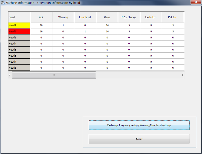
(2) Screen displayed when a warning is issued or an error occurs
When a value in the “NZL. Change” cell exceeds that in the “Warning” cell, the head is
displayed in yellow. When a value in the “NZL. Change” cell exceeds that in the “Error level”
cell, the head is displayed in red.
The signal light lighting condition does not change.
Part 2 Detailed Description of Each Function Chapter 10 Machine Management Information
10-16
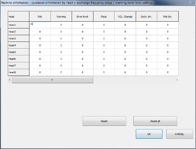
(3) Exchange frequency setup
When you press the <Exchange frequency setup> button or select [Set] – [Setting – Head
operation information] in the menu, the exchange frequency setup screen appears. When
the head nozzle was changed, the setting can be initialized by setting the number of changes
of the changed head nozzle to zero.
The setting can be executed when the user level is set to Serviceman.
1) Press the item to be updated or press a number key after moving the cursor by the
direction key of the software keyboard, and the target cell will be active so that it can be
edited.
2) If you press the <ESC> key when the cell is active, the data being changed is cancelled.
3) If you press the <ENTER> key or the <TAB> key when the cell is active, a value you
have entered is validated.
4) Press the <OK> button to check data and close the exchange frequency setup screen.
5) Press <CANCEL> to revert nozzle usage information to the original and close the
exchange frequency setup screen.