RS-1_instruction manual.pdf - 第1020页
Part 2 D etaile d Descript ion of E ach Functi on Chapter 12 Handling th e Optional Device s 12 - 136 - A pplicab l e compo nent and applicab le pac kage size ・ Applica ble compone nt and package size Nozzle number Appli…
Part 2 Detailed Description of Each Function Chapter 12 Handling the Optional Devices
12-135
12.19.2 Specifications
(1) Required parts and software
- USB memory containing a nozzle information file that is supplied to the customer
together with the nozzle in the same package
- Gripper nozzles that are appropriate for the shape and size of each component and the
shape of a feeder unit (such as tape and tray)
(See “(5) Applicable components and packaging style.”)
(2) Method
Centering method: Laser
(3) Component placement precision
Component placement precision : ± 0.3 mm or less (3 σ)
Note that the attained precision may vary depending on the shape of a component.
When the system places a component whose portion to be aligned with laser has an
edge, whose molded part has a burr, or whose portion to be inspected with the system
cannot be fixed to a pick-up device, the precision described above cannot be attained.
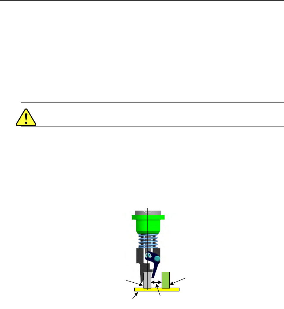
(4) Limited adjacent components
When the system places a component, a gripper swing arm opens, so it may be in contact
with an adjacent component.
Therefore, there are the following two restraints on operations of a gripper nozzle:
- The height of a component to be placed with a gripper nozzle should be 3 mm or higher
than that of adjacent components.
- The side of a component to be held with the swing arm of the gripper nozzle should be
far from adjacent components by 4 mm or more.
(See the figure below.)
(5) Applicable components and packaging style
Applicable components:
• Connectors
(the top side cannot be picked up with a standard nozzle)
• Lead pitch (1 mm or wider)
• Weight: 5 g or less
(This value is subject to change depending on the shape of a component.)
• There should be a flat area on the top of a component against which the fixed arm
can be pushed. (to prevent a component from inclining when the X-Y axes moves)
Packaging style:
• Taping and tray
Component B
Component A
Note: Components A and B should
another by at least 4mm.
Board
Part 2 Detailed Description of Each Function Chapter 12 Handling the Optional Devices
12-136
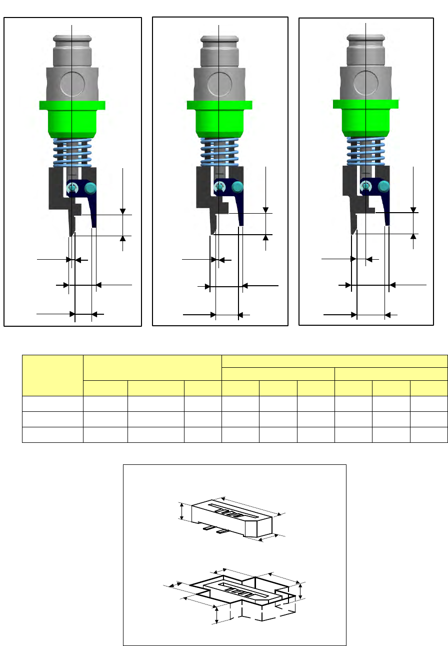
- Applicable component and applicable package size
・Applicable component and package size
Nozzle
number
Applicable components
Packaging style (Dimensions of an embossed part)
Fixed arm side
Swing arm side
X
Y
H
A
B
C
D
E
F
7689
6
~
0.8
~
2.2
5
~
1.5
~
5.6
~
4
~
3
~
5.6
~
2.5
~
7690
6
~
1.8
~
3.2
5
~
1.5
~
5.6
~
4
~
3
~
5.6
~
2.5
~
7691
6
~
2.8
~
4.2
5
~
1.5
~
5.6
~
4
~
3
~
5.6
~
2.5
~
H
X
Y
A
D
E
B
F
C
0.5
4.7
2.8
3.5
No. 7689 nozzle
0.5
5.7
3.8
3.5
No. 7690 nozzle
1.5
6.7
4.8
3.5
No. 7691 nozzle
Part 2 Detailed Description of Each Function Chapter 12 Handling the Optional Devices
12-137
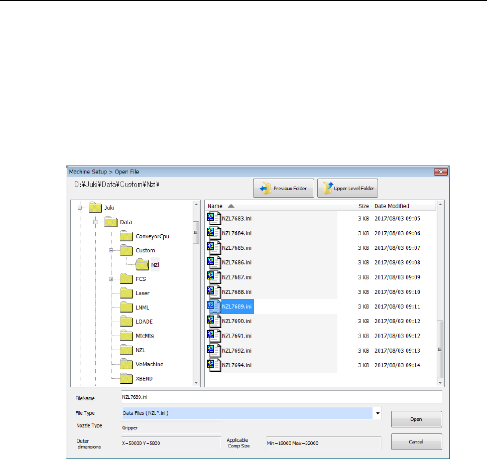
12.19.3 How to Use
(1) In Machine setup, the gripper nozzle information is read from the USB memory attached to
the nozzle.
If any USB memory is not supplied with the purchased special nozzle, or if the USB memory
malfunctions or is lost, check D:¥JUKI¥DATA¥Custom¥Nzl.
* Once you load information, it is stored on the machine, so you do not have to perform this
operation every time you use the machine.
◇ Select the [Read Nzl. data] command from the “File” menu invoked from the “Machine
setup” menu, and load the nozzle information file for a gripper nozzle on the following
dialog box. (See Section 8.3.2.2 “Read Nzl. data (read nozzle data).”)