RS-1_instruction manual.pdf - 第413页
Part 1 B asic O peration Chapter 4 Cr eating a Produc tion Progra m 4- 78 (6) Inspection 1 This tab she et allows you to set the f ollowing item s: “T ombstone, ” “Compo nent Angl e ” and “Pick Position D etection. ” 1) …
Part 1 Basic Operation Chapter 4 Creating a Production Program
4-77
7) Component skip
When you select the <Yes> button for this “Component skip” field, the system skips the
corresponding component during production and does not place it on a board.
The placement data record for a component specified to be skipped on the database is not
used for PWB production, but it is not listed on the “Not placed” list.
When you load the component information from the database, the <No> button is
selected for this “Component skip.”
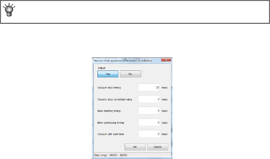
8) Vacuum time adjustment
Specify whether to adjust the vacuum time or not.
When you press the <Setting> button, the following screen appears.
When you select the <Yes> button for the menu item “Adjust,” you can enter an adjustment
value for each item of “Vacuum stop timing,” “Vacuum stop correction value,” “Blow starting
timing,” “Blow continuing timing” and “Vacuum OFF wait time” in milliseconds.
9) Control
Specify how to control the stroke to be applied to placement of a component.
When a nozzle for controlling low load is selected on the “Centering” tab, the <Low load>
button and the <Load graph> button are enabled on the screen.
When you select the <Low load> button for this menu item, the input unit for the menu item
“Placing stroke” is changed to [g], and the setting of the “Place Z down” field of the menu
item “Speed” is changed to “FC speed.”
When you press the <Load graph> button, you can check the pressure that can be applied
with the nozzle.
Part 1 Basic Operation Chapter 4 Creating a Production Program
4-78
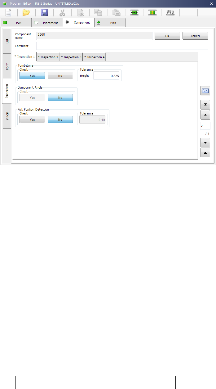
(6) Inspection 1
This tab sheet allows you to set the following items: “Tombstone,” “Component Angle” and “Pick
Position Detection.”
1) Tombstone
Specify whether to check that a component stands on its side (“Tombstone” error).
Normally, we recommend that you select the “Yes” radio button for a 3216 chip component
or smaller ones. Therefore, when you select a “Chip” as the “Component type,” the system
automatically selects the “Yes” radio button.
“Tolerance”: The system automatically enters a value calculated from the component
height you entered to this field.
2) Component Angle
This specifies whether to perform or not SOT component direction inspection defined by
general-purpose vision component. The direction inspection of the first component before
production and after “no components” can be performed.
Perform this check mainly to check that a correct component is not set.
Only for the general-purpose vision components whose number of element groups of lead
component is 3 or less or whose number of outer/inner lead elements is 2 or more, this
function can be selected.
3) Pick Position Detection
This function detects whether the center of a component is shifted by a value more than that
set in the “Tolerance” field when viewed from the center of the nozzle.
This function is available only if the packaging style is a tape feeder. Otherwise, this
function is disabled. Select the “Yes” radio button for the desired component, and enter the
value in the “Tolerance” field as the judgment value.
The range of a value you can enter in this field is from 0 to the length of a component (or
width of a component if the component supply angle is 90º or 270º).
When you select the “Yes” radio button, the default value to be set in the “Tolerance” field is
calculated with the expression shown below:
Length (or width) of a component ÷ 2 × (set value/100)
The “set value” is set in the “Environment setting” screen of the Program Editor. The
default is 50 (%).
Part 1 Basic Operation Chapter 4 Creating a Production Program
4-79
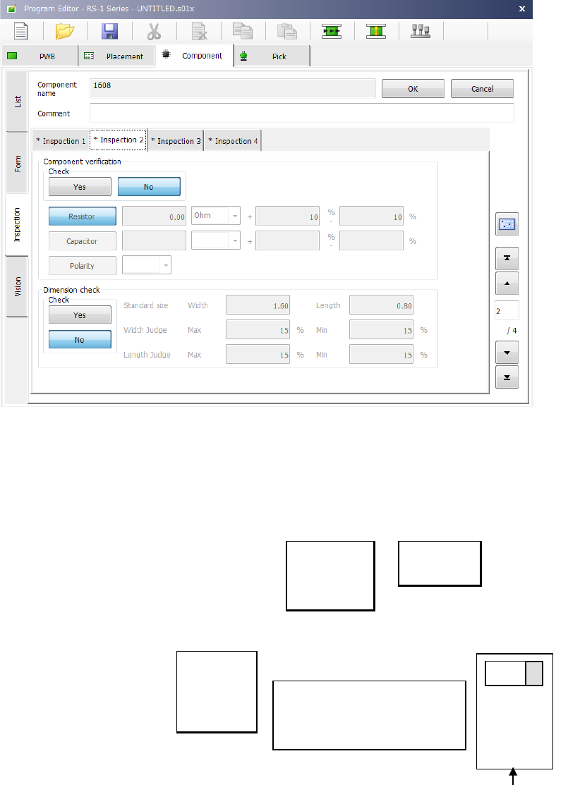
(7) Inspection 2
This tab sheet allows you to set the following items: “Component verification” and “Dimension
check.”
1) Component verification (option)
This item is mainly used to check a component setting error. Select whether to verify a
component or not with the corresponding button, <Yes> or <No>.
When you select the <Resistor> button or the <Capacitor> button, enter the threshold value,
the unit and the lower/upper limit of the allowable error. Select the unit from the drop-down
list.
Ω
PF
KΩ
μF
MΩ
When you select the <Polarity> button, you can select the direction from the drop-down list.
Right
Top
Left
Bottom
2) Dimension check
Specify whether to perform a dimension check of a component or not with the corresponding
button, <Yes> or <No>.
Specify the length and the width of a component in the “Standard size” fields. Specify the
allowable maximum difference and the minimum difference between the values set in the
“Standard size” field and the value measured actually in the “Width Judge” fields and the
“Length Judge” fields in % respectively.
Main unit side
+
Set the direction of the positive
electrode viewed from the
component supply direction
(packaging style)
Tape feeder