RS-1_instruction manual.pdf - 第563页
Part 1 B asic O peration Chapter 4 Cr eating a Produc tion Progra m 4- 228 2) If the density is abnorm al The follow ing error me ssage appear s if the shado w density of the cav i ty is abnorm al. 3) If the center of th…
Part 1 Basic Operation Chapter 4 Creating a Production Program
4-227
(10) Component direction inspection under tracking
While tracking is temporarily stopped, it is possible to execute component direction
inspection.
While the component direction inspection is in process, the following screen is displayed.
After the end of the SOT direction inspection or component direction inspection, the
inspection result is displayed as “OK” or “NG.”
See “(2) SOT Angle” of “(6) Inspection 1” of Section 4.3.5.2 “Creating of component data” of
Chapter 4 for settings of inspection.
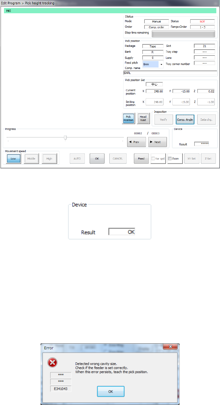
(11) Automatic teaching during tracking of a component pick-up position
You can perform the automatic teaching function when the system temporarily stops tracking a
pick-up position.
The system displays the following five error/question dialog boxes during automatic teaching.
1) If the size is greatly different
“Cavity” means a depression in which a component is put.
If the component size is different from the cavity size greatly, the following error message
appears on the screen.
Part 1 Basic Operation Chapter 4 Creating a Production Program
4-228
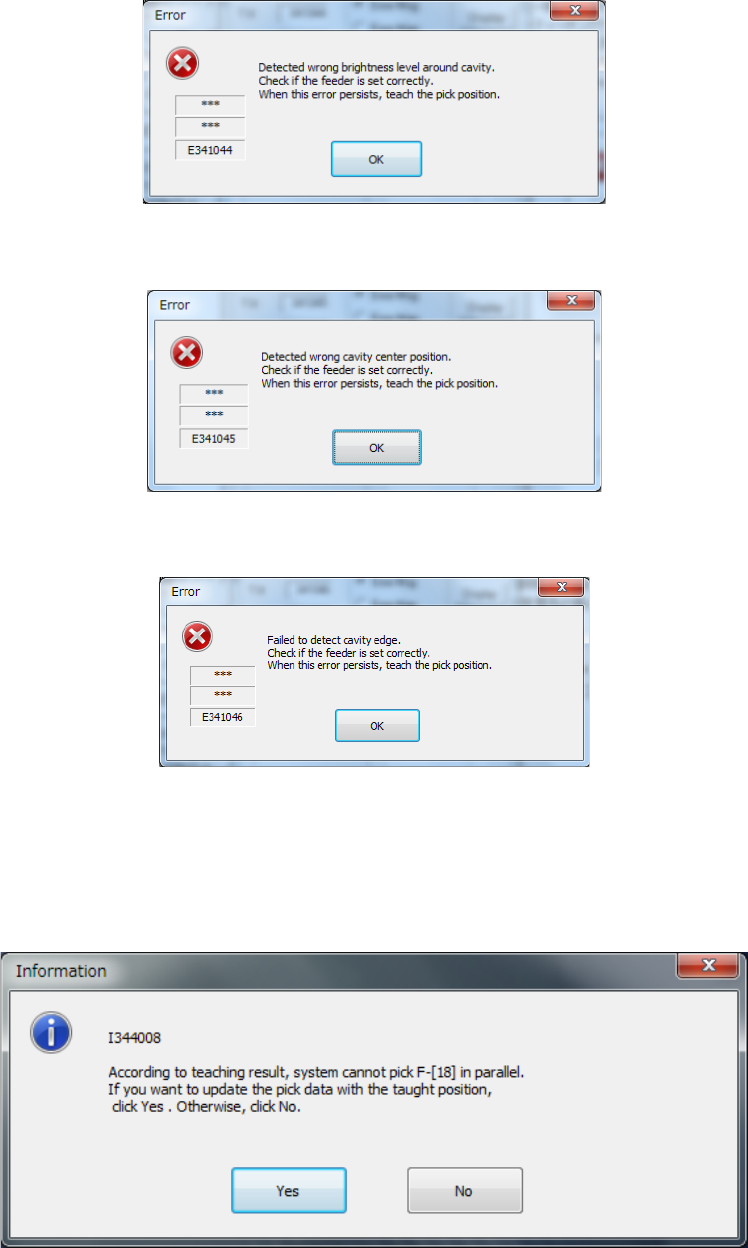
2) If the density is abnormal
The following error message appears if the shadow density of the cavity is abnormal.
3) If the center of the cavity is shifted from the regulated position
The following error message appears if the pick data you set is quite different from the pick
data corrected with the automatic teaching function.
4) If the system failed to detect the cavity edge
The following error message appears if the system fails to detect the cavity shadow
rectangular frame.
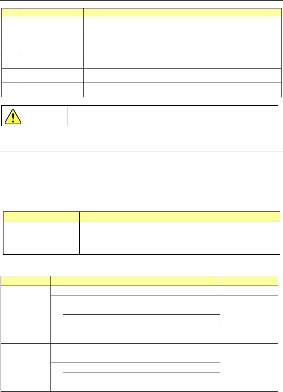
5) If the system cannot pick up two or more components simultaneously after performing the
automatic teaching function
The following question message appears if the system cannot pick up two or more
components simultaneously.
If you give preference to the accuracy over the cycle time, select the <Yes> button.
Otherwise, select the <No> button.
Part 1 Basic Operation Chapter 4 Creating a Production Program
4-229
4.5.7 Measurement/Inspection
No.
Submenu
Overview
1
Current component
Measures each detailed value of the Component data
2
All component
Measures each detailed value of two or more Component data records.
3
PWB Height
Measures the height of the surface of a PWB at a component placement position.
4 Recognize
Recognizes a component with a VCS to check to see if the component can be
centered.
5 Verify speed
Performs quasi-production operation to check errors of the moving XYθ-axes
during operation.
6 Vision teaching
Measures a ball of a ball component (general-purpose vision component, BGA
and FBGA).
7 Bad mark teaching
Use the OCC unit to teach a mark in order to determine whether to produce a
circuit.
To avoid a risk of injury, do not put your hands inside the machine or move
your face or head close the machine while the system is teaching data.
4.5.7.1 Current component/All component (Single measurement/Continuous measurement)
These functions cause the system to pick up an actual component to measure it with laser or a
VCS, and then reflect the measured data into a production program.
(1) Measurement mode
Two types of modes are provided for measurement operation: “Continuous Measurement” and
“Single Measurement.” Select the desired mode from the menu.
The command and its corresponding measurement mode are shown in Table below:
Measurement mode Description
Single Measurement Measures a component displayed on the Component "Form" screen.
Continuous Measurement Measures all components/components which satisfy the conditions specified in a
production program. In Single Measurement mode, you can measure a
component which failed to be measured for some reason individually.
(2) Measurement items
The items to be measured are outlined in the table below.
Measure item What to measure Remarks
Comp. height
Component height -
Calculation of the optimal laser centering value
Components to be
centered with laser
only
Laser height
Threshold value for a chip tombstone error
Outline
Outer dimensions of a component (length and width) -
Calculation of the optimal nozzle number -
Vacuum level Vacuum level to be applied when an actual component is picked up -
Lead Information
Dimensions of a lead of a component
Components to be
centered with a VCS
only
Lead pitch
Lead length
Number of leads/information on a missing lead(s)
CAUTION