RS-1_instruction manual.pdf - 第405页
Part 1 B asic O peration Chapter 4 Cr eating a Produc tion Progra m 4- 70 6) Speed Select the spe ed at which the Z - axis m oves when a component is picked u p. When you se lect load con trol, the pick descent speed is …
Part 1 Basic Operation Chapter 4 Creating a Production Program
4-69
3) Picking offset X, Y
If you want to shift the component pick-up position from the center of a component because
the machine cannot pick the center of the component or for any other reason, set the
“Picking offset X, Y.” Set the distance from the center of a component to the component
pick-up coordinates to be applied when the component is picked up in the “X” and “Y” fields
of the “Picking offset” menu item. Each value is added to or subtracted from the initial
value of the “X” coordinate and that of “Y” coordinate automatically calculated when you
create Pick data.
Since the settings of the “Picking offset X, Y” are to be used to decide the recognition
window for recognizing a component or to check a component pick-up position error, it is
recommended to set them if the center of the component is different from the component
pick-up position.
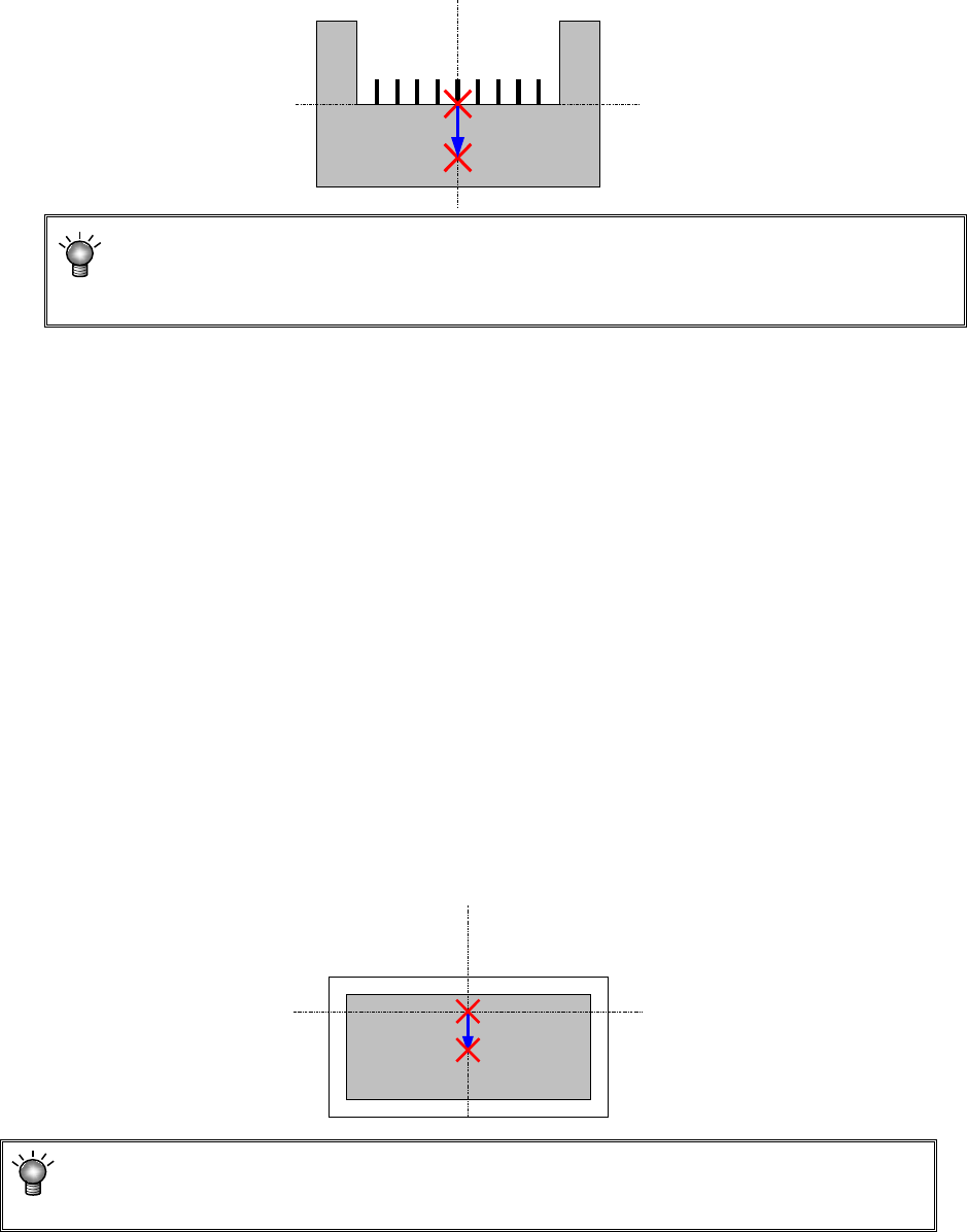
4) Picking offset Z
Specify how much to push the tip of the nozzle from the pick-up height when a component is
picked up. This value is used to automatically calculate the “Z” coordinate of the “Pick
position” of the Pick data. If you change the value set in the “Z” coordinate of the “Picking
offset” even though the pick-up coordinates are already completed, the system does not
calculate the pick-up coordinates again. When you change the setting of the menu item
“Side” of the Pick data corresponding to the changed Component data to “AUTO” and
specify the pick-up position again, the system calculates the pick-up coordinates again, and
changes the value in the “Z” field also.
5) Pick-up coordinate offset
If you have to shift the component pick-up position from the default position X, Y in order to
pick up the center of a component, set the “Pick-up coordinate offset (X, Y).” The function
of a coordinate Z is not different from that of the “Picking offset Z.” Enter a correction value
to be applied to each initial value that is automatically calculated when Pick data is created.
Set the distance from the pick-up coordinates calculated automatically to the center of a
component and the height in the “Pick-up coordinate offset” fields. Each value you set in
these fields are added or subtracted to/from the corresponding initial value automatically
calculated when Pick data is created. Set these fields if any of the initial values of the
component pick-up coordinates is shifted from the center of a component or the component
pick-up height.
When you set both the “Picking offset” and the “Pick-up coordinate offset,” the total of
these offsets is reflected in automatic calculation of the pick-up coordinates as a value to
be added or subtracted.
Part 1 Basic Operation Chapter 4 Creating a Production Program
4-70
6) Speed
Select the speed at which the Z-axis moves when a component is picked up.
When you select load control, the pick descent speed is changed to "FC speed."
7) Auto correct pick
For tape components to be centered with laser, this function corrects a pickup mis-position
automatically based on the recognition result.
The corrected position is entered to the coordinates field of the component pick-up position
on the “Pick” data screen when you select the <Yes> button.
CAUTION
For a component whose center is not picked up, select “No” as the
“Auto correct pick” (select “No” also if you enter the “Picking offset”).
The system corrects the component pick-up position without causing the simultaneous
pick-up to be disordered by correcting the pitch in Y direction when an electric feeder is
used.
8) Auto teaching
This is the function for automatically measuring the center of a component when the system
tracks the component pick-up position.
For square chips 0402 to 3216 whose packaging style is an 8-mm paper tape or 8-mm
emboss tape, you can set [Yes].
However, the default setting is [No] as the auto teaching cannot be performed in accordance
with the color or shape when the packing style is an emboss tape.
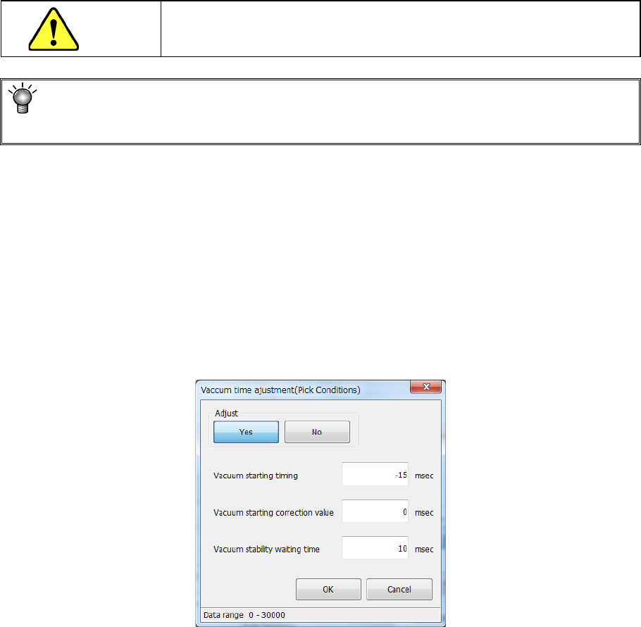
9) Vacuum time adjustment
Specify whether to adjust the vacuum time or not.
When you press the <Setting> button, the following screen appears.
When you select the <Yes> button for the menu item “Adjust,” you can enter an adjustment
value for each item of “Vacuum starting timing,” “Vacuum starting correction value” and
“Vacuum stability waiting time” in milliseconds.

Part 1 Basic Operation Chapter 4 Creating a Production Program
4-71
10) Component cueing
Specify whether to cue (head) each component and/or whether to specify a threshold value.
When a component can be cued, you can specify this menu item, and “Yes” is selected by
default.
Data on a component that can be cued is shown below:
<Cueing of a component with the OCC>
1. 8-mm paper tape or 8-mm embossed tape
2. Component type: Chip (square chip)
3. 0402 to 3216 (0.35 mm ≦ longer side ≦ 3.4 mm, 0.10 mm ≦ shorter side ≦ 1.8
mm)
The menu item “Threshold value” is set to “Not Used” by default.
If a component cannot be cued (headed) with the OCC well, you can specify a threshold
value for detecting existence of a component individually.
Not Used (default)
Select this button if you do not specify a threshold value for detecting
a component to be cued with the OCC individually.
The system operates according to the setting of the main unit.
Used
Select this button if you do not specify a threshold value for detecting
a component to be cued with the OCC individually.
The system operates according to the setting of a production
program.
The default value of the “Threshold value” is 30. You can specify a value in the range of 0
to 40.
11) Control
Specify how to control the stroke to be applied to pick-up of a component.
When a nozzle for controlling low load is selected on the “Centering” tab, the <Low load>
button and the <Load graph> button are enabled on the screen.
When you select the <Low load> button for this menu item, the input unit for the menu item
“Pick stroke” is changed to [g], and the setting of the “Pick Z down” field of the menu item
“Speed” is changed to “FC speed.”
When you press the <Load graph> button, you can check the pressure that can be applied
with the nozzle.