RS-1_instruction manual.pdf - 第220页
Part 1 B asic O peration Chapter 2 Pr oduction 2- 109 (8 ) PWB set Press the < PWB se t > butt on, and the board will be l oaded or re - clam ped. If any board is not l oade d to the machine y et, the messag e “PWB…
Part 1 Basic Operation Chapter 2 Production
2-108
Suspended circuit No.
Displays the number of a circuit on which a component placement is aborted with the
selected station.
Suspended step No.
Displays the number of a step in which a component placement is aborted with the
selected station.
(3) PWB set
Clamps a board of which the placement positions are to be checked.
Menu item Description
PWB set Loads a board/re-clamps a board.
(4) Placement Display
Placement operation displayed on the list above is superimposed on the screen.
Menu item
Description
Current
When you press the <START> switch, the selected component placement position is
displayed.
All
When you press the <START> switch, the system starts displaying component
placement positions from the selected one.
When you press the <STOP> switch, the system stops displaying component
placement positions.
Interval (100ms)
Enter the time period when the system has to wait before it moves to the next
component placement positions in Continuous Tracking mode.
Always
This button always displays the component placement position that is being selected.
When you change the selected position, the system displays the changed component
placement position.
Zoom
This button allows you to select whether to zoom the displayed component
placement position or not.
BOC mark recognition
The system recognizes a BOC mark if necessary before displaying a component
placement position.
Area mark recognition
The system recognizes an area mark if necessary before displaying a component
placement position.
(5) Placement Movement
You can select a component placement position from the list.
Menu item
Description
Previous
Selects the component placement position immediately before the selected one.
If the selected position is the first position, this button does not function.
Next
Selects the component placement position immediately after the selected one.
If the selected position is the last position, this button does not function.
(6) Placement tracking
Set a component placement position selected on the list as a position on which a component is
already placed or not.
Menu item
Description
Not placed
Any component is not placed on the selected placement position.
The system will place a component there with continuous production.
Placed
A component is placed on the selected placement position.
The system will not place any component there with continuous production.
(7) Superimpose
The system will superimpose the selected component placement position on the screen.
Part 1 Basic Operation Chapter 2 Production
2-109
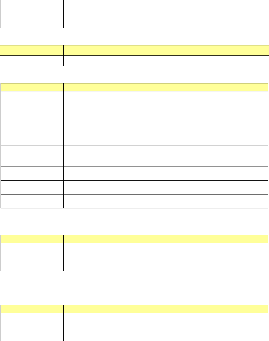
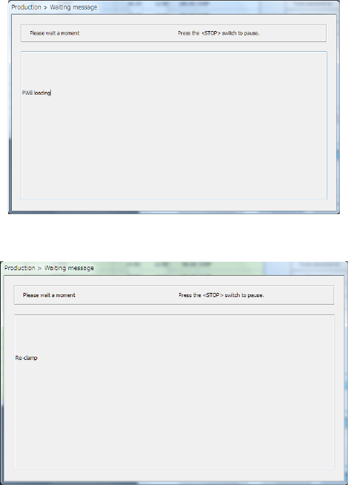
(8) PWB set
Press the <PWB set> button, and the board will be loaded or re-clamped.
If any board is not loaded to the machine yet, the message “PWB loading” appears on the
screen.
If a board is already set, the message “Re-clamp” appears on the screen.
(9) Moving/displaying/checking a component placement position
Select a desired component placement position from the list, or use the <Previous> button or
the <Next> button to select a component placement position to be displayed/checked.
If you check the <Always> button, the selected component placement position is displayed on
the screen when you select it.
Check the displayed component placement position to select the <Not placed> button or the
<Placed> button.
When you select the <Current> button, and then press the <START> switch, the corresponding
head moves to the selected component placement position, and the system displays this
component placement position on the superimpose screen.
When you select the <All> button, and then press the <START> switch, the system selects all
placement operations following the placement operation that is being selected now to the last
one sequentially. Then, the system moves the head to each placement position, and displays
it on the superimpose screen. After it waits for the time specified in the “Interval” field, it
selects the next component placement position.
While the system is operating, you cannot use any button displayed on the dialog box above.
To interrupt the operation, press the <STOP> switch.
Part 1 Basic Operation Chapter 2 Production
2-110
Verify check
Overview
Select the [Support] command from the “Product” menu, and then the [Verify Current check]
command or the [Verify All check] command from the “Support” menu.
The system attaches an actual component on the head and compares the resistance value,
capacity and polarity stored in a production program (Component data) with those of the attached
component to inspect them. Be sure to perform this type of check after setting the feeders on the
feeder bank.
Verify check type
Description
Single check mode
When you select the [Verify Current check] command from the “Support” menu, the system
performs a verify check for the specified component only. In addition, the system
separately checks a component at which it detected an error on Continuous Check mode.
Continuous check
mode
When you select the [Verify All check] command from the “Support” menu, the system
checks components that satisfy your requirements among all components whose data is
stored in the production program.
- In Single check mode, the system can check a component that failed to pass this check
for some reason.
Operations
(1) Head used to pickup a component
The system does not perform measurement with two or more heads at the same time. The
head used to pick up a component is automatically selected.
(2) Returning/discarding a component after checking it
The system returns some checked components onto their original positions, and discards
other ones depending on their packaging style as shown in Table below.
Where to discard a component is determined according to the setting of “Compo Reject to” on
the Component data screen. Since a component whose size is 1 mm or less may stand on
its side or may be turned upside down when it is returned to the original position, the system
displays the “Question” screen to ask you how it should handle a component.
Note that you cannot pick up a component manually.
Packaging style Condition
Returning a
component
Discarding a
component
Tape
The short side length of the external size is 1 mm or less.
“Question” screen *1, *3
The short side length of the external size is 1 mm or more.
○ ○
*2, *3
Holder
―
○ ○
*2
MTC
―
○ ○
*2
MTS
―
○ ○
*2
*1 The system displays the screen to ask you whether to return a component or discard it. When
the system enters Continuous measurement mode, it displays this “Question” screen before
continuous measurement.
*2 The system discards a component when you select “IC collection belt” or “Protect” in the menu
item “Comp reject to.”
*3 A component is discarded when the feeder type is a stick feeder.
(3) Selecting a feeder used to pick up a component
If two or more feeders are assigned to the same type of components on the Pick data screen,
the system starts picking up components from one whose data was entered first of all by
default. Only in Single check mode, you can change the feeder used to pick up a component
intentionally.
(4) Changing the coordinates of a component pick-up position
If a component cannot be picked up normally, manually enter the coordinates of a component
pick-up position or teach them to change them.