RS-1_instruction manual.pdf - 第984页
Part 2 D etaile d Descript ion of E ach Functi on Chapter 12 Handling th e Optional Device s 12 - 100 12.14.7 Editing sub - functions Start up th e Program Edit or, and th en select the “ Component ” data screen. Next, s…
Part 2 Detailed Description of Each Function Chapter 12 Handling the Optional Devices
12-99
12.14.6 Data editing
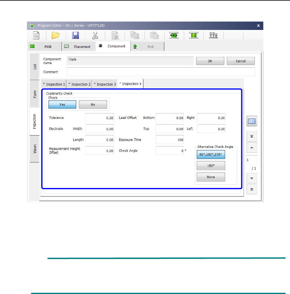
Start up the Program Editor, and then select the “Inspection 4” tab on the “Component” data screen.
Set the menu items displayed on the “Coplanarity check” column.
* See Section 4.3.5.2 (10) “Inspection 4” of Chapter 4 “Creating a Production Program” for
details of inspection.
When the lead width is less than 0.3 mm, enter the correct lead width and the correct
electrode size on the “Component” data screen. Or, the machine may not be able to
detect a terminal correctly. Be sure to enter the correct values.
Part 2 Detailed Description of Each Function Chapter 12 Handling the Optional Devices
12-100
12.14.7 Editing sub-functions
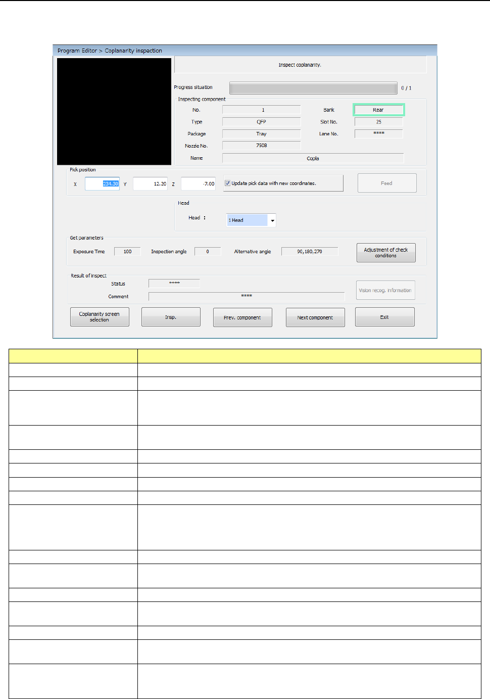
Start up the Program Editor, and then select the “Component” data screen. Next, select the
[Meas/Insp] command, and then the [Coplanarity inspection] command.
Item
Description
Component being inspected
Displays data on a component whose coplanarity is to be checked.
Pick position
Displays data on a position from a component is picked up.
Update pick data with new
coordinates.
Select whether to update Pick data with the taught results.
When you do not place a checkmark in this check box, the coordinates are applied
to Pick data this time only.
<Feed> button
Knocks a feeder once to feed components (except for components supplied with a
32-mm paper tape).
Head
You can select a head used to run a coplanarity check.
Exposure Time
Displays the exposure time of the camera built into the coplanarity sensor.
Inspection angle
Displays the coplanarity check angle.
Alternative angle
Displays the coplanarity alternative check angle.
Status
Displays the result of a coplanarity check.
OK: No error
NG: Error
****: A coplanarity check has not been run yet.
Comment
Displays the cause of an error if it occurs as a result of a coplanarity check.
<Vision recog. information>
button
Displays the recognition information obtained when a component is recognized with
a VCS.
<Insp.> button
Runs a coplanarity check.
<Prev. component> button
Changes the component pick-up position to that of the previous alternative
component.
<Next component> button
Changes the component pick-up position to that of the next alternative component.
<Exit> button
Quits a coplanarity check, and then switches the current screen to the previous
screen.
<Adjustment of check
conditions> button
If the machine does not run a coplanarity check stably, this button automatically
adjusts the inspection angle and the exposure time to obtain parameters that make
the machine measure a component stably.
Part 2 Detailed Description of Each Function Chapter 12 Handling the Optional Devices
12-101
12.14.8 Production
The machine runs a coplanarity check during PWB production, trial production and dry run
operation.
A coplanarity check does not inspect a component actually during dry run operation.
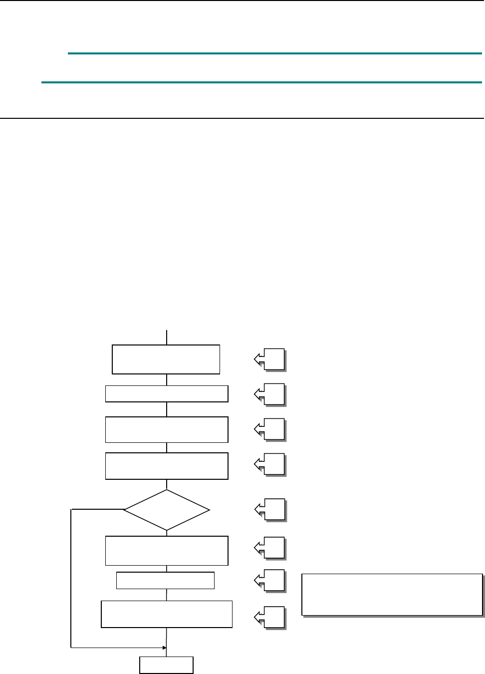
12.14.8.1 Procedure for a coplanarity check
① Picking up of a target component
② Moving to a VCS position
③ Recognition of an image of a component with a VCS
④ Moving to the measurement start position of the coplanarity sensor
⑤ Checking to see if the machine can run a coplanarity check for a component
⑥ Position correction according to the result of recognition of an image
⑦ Coplanarity check of a component
⑧ Determination of acceptance of a component based on the result of measurement with the
coplanarity sensor
[Process to be executed after determination of acceptance of a component]
⑧-1 Discarding of a component
⑧-2 Placement of a component on a board
⑧-3 Pause
See the process flowchart
(flowchart of a coplanarity check)
on the next page.
Picking up of a target
component
Moving to a VCS position
Recognition of an image of
a component with a VCS
Moving to the coplanarity
sensor position
Coplanarity check
Determination of acceptance
of a component
End
Correction of the
component position
Checking of a
component
①
②
③
④
⑤
⑥
⑦
⑧