RS-1_instruction manual.pdf - 第658页
Pa r t 2 D et ai l ed Des c r i pt i o n of Ea c h F unc t i o n Chapte r 6 G e neral - Purpose Vision Co mpone nt 6- 27 Pr oce du re f or cre ati n g gen eral - pur p os e visi on c omp on en t dat a 6.5 Lead comp onent…
Part 2 Detailed Description of Each Function Chapter 6 General-Purpose Vision Component
6-26
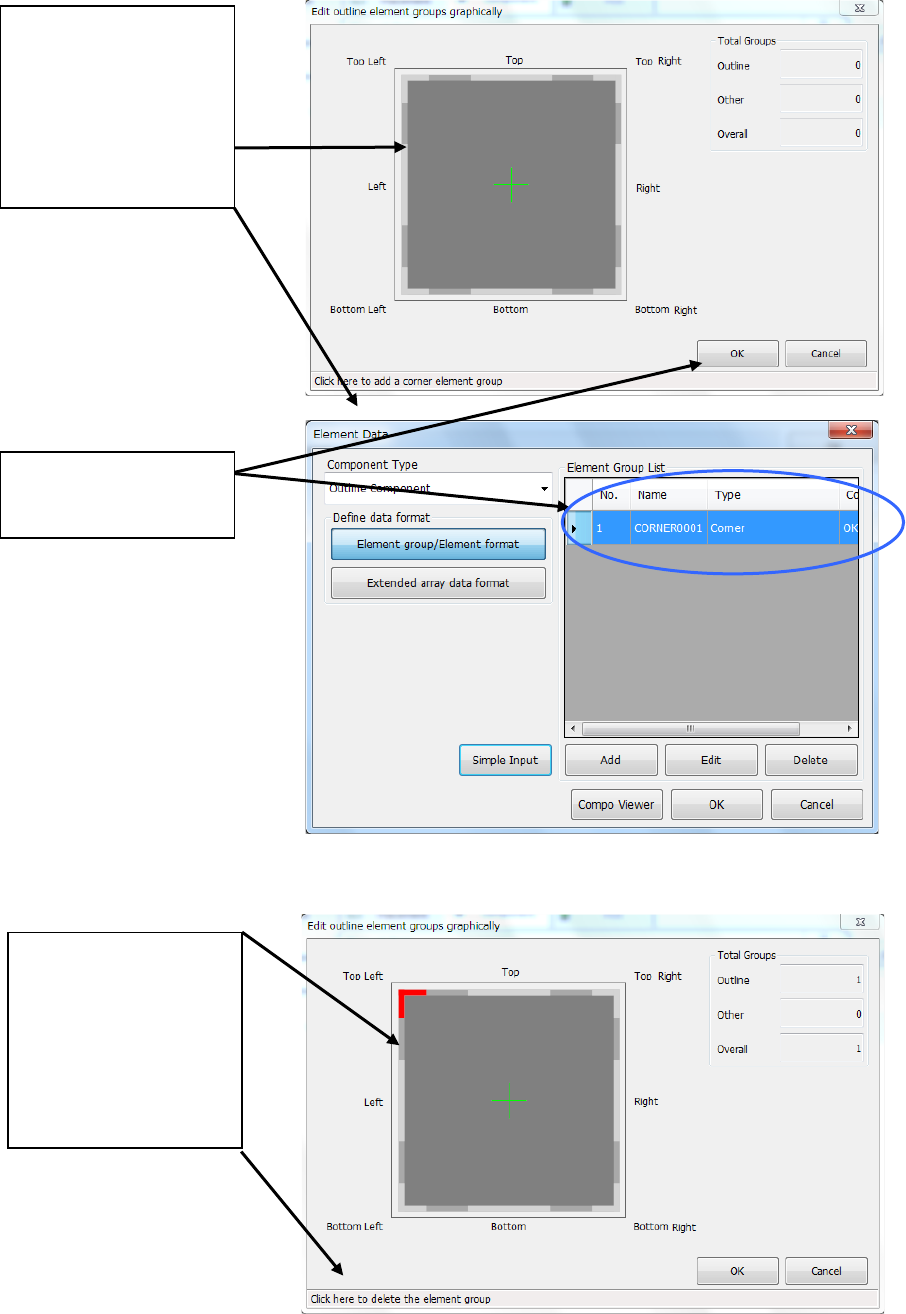
(2) Adding an element group
(3) Deleting an element group
When you touch the <OK>
button, the system creates
an element group.
When you place the mouse
pointer at the position
around the corner or side
where you can delete an
element group, the mouse
pointer changes to the
hand-shaped cursor and the
message appears on the
bottom of the dialog box.
Touch this position.
When you place the mouse
pointer at the position
around the corner or side
where you can add an
element group, the mouse
pointer changes to the
hand-shaped cursor and the
message appears on the
bottom of the dialog box.
Touch this position.
Part 2 Detailed Description of Each Function Chapter 6 General-Purpose Vision Component
6-27
Procedure for creating general-purpose vision component data 6.5
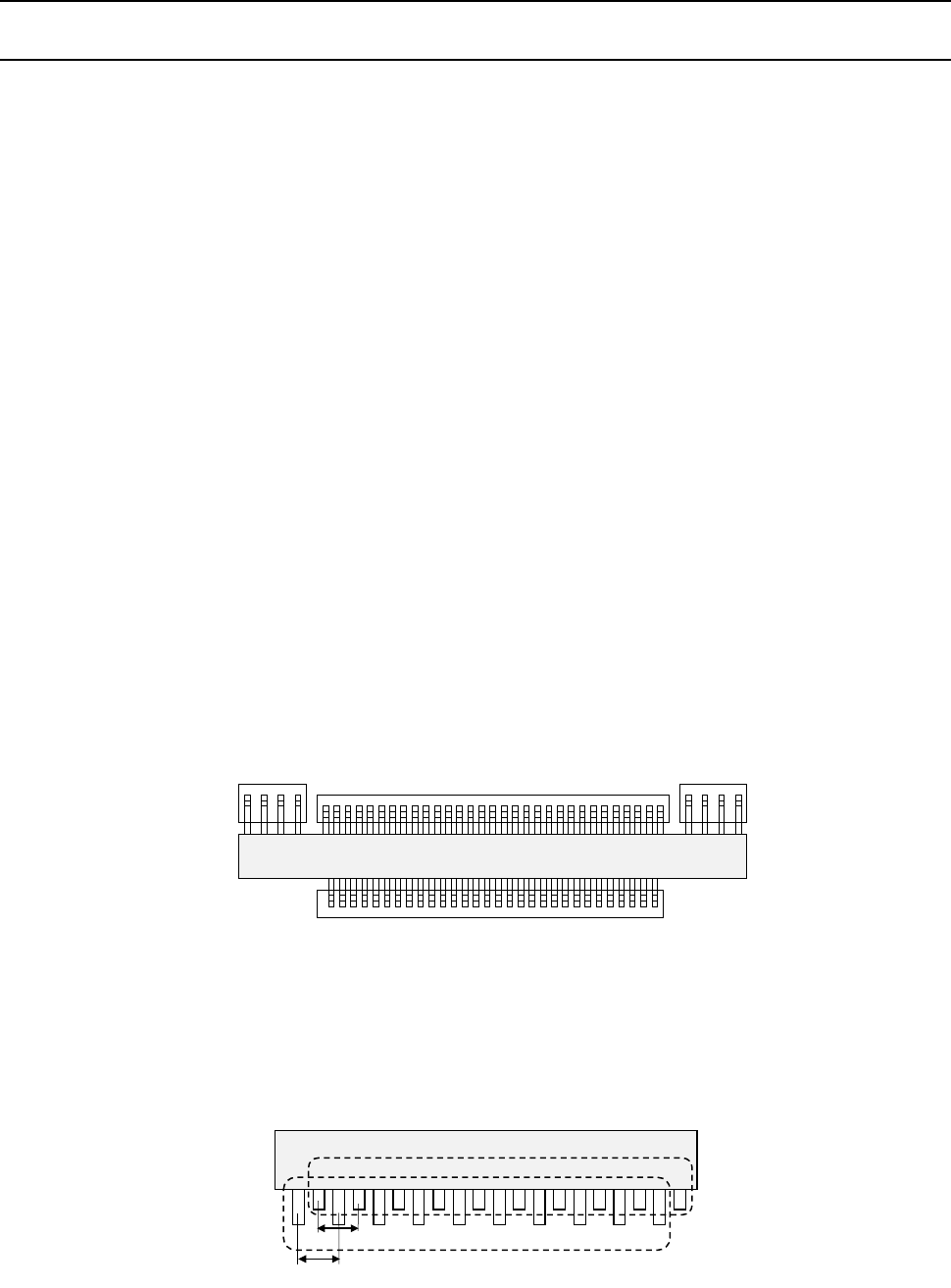
Lead components (Element group/Element format) 6.5.1
This section describes the procedure for creating data on lead components (multi-lead
components).
1. Operation on the “Element Data” screen
- Select “Lead Component” on the “Component Type” combo box.
- Check the “Element group/Element format” check box in the “Define data format” field.
- Click the <Add> button on the “Element Group List.”
2. Operation on the “Element Group” screen
Define an element group on this screen.
An element group is composed of components whose lead size and pitch are the same.
•
Description
In the example below, four element groups are defined. The size and pitch of leads of the
first and third element groups are the same, while the direction and position of leads of these
groups are different from each another. The size and pitch of leads of the second and
fourth element groups are the same also, but leads of these groups are not arrange
continuously, so the lead pitch is not the same. If the distance between these leads is an
integral multiple of the specified pitch, they can be defined as one element group that has an
area having no lead. However, we recommend that you define them as separate element
groups.
To define the direction and position of the element group, specify the component posture.
The direction of a component shown in the figure below shall be normal. The posture of
multi-lead components is regulated from the top view.
If the length of a lead changes alternatively as shown in Figure define two groups: one having
long leads and another having short leads. The pitch is also defined for a group of long leads
and that of short leads separately.
Fourth element
group
Third element
group
Second element
group
First element
group
Top View
First element group
Pitch 2
Pitch 1
Second element group
Part 2 Detailed Description of Each Function Chapter 6 General-Purpose Vision Component
6-28
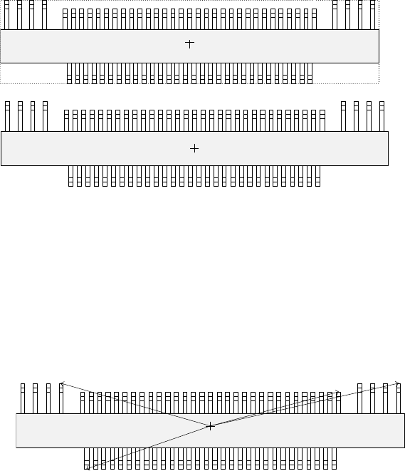
①
Name
Name an element group to be handled. When you want to change an element group,
specify its name to edit it.
- A name is assigned automatically with serial numbers.
- Users can change this numbered name to an alphanumeric name (up to 32 characters).
In the example, the numbered name is used.
②
First element position
Specify the position (X, Y) and direction (Theta) of an element group.
As the position, specify the distance (offset) from the center of a component. Normally, the
center of a component is the center of the component outline.
- If the placement coordinates set in Placement data of a production program is not based
on the center of the component outline, you can specify the coordinates of the reference
component center with coordinates different from the center of the component outline.
Figure 6.5.1.3 indicates that the center of the component outline is the center of a
component, while Figure 6.5.1.4 indicates that the center of component body is the
center of a component.
- To be precise, the “First element position” is the distance (offset) from the center of a
component to the first element.
In the same manner as defined for a standard lead components (such as a QFP, SOP
and connector), the first element is the leftmost element when an element group is
located on the bottom side, the lowest element when located on the right side, the
rightmost element when located on the top side, or the top element when located on the
left side. The figure below shows the first element position of the component.
For a lead element, the first element position is the end of the first lead with being
viewed from the center of a component.
- The direction (angle) of an element group is 0 degrees when it is located on the bottom
side, 90 degrees when located on the right side, 180 degrees when located on the top
side, and 270 degrees when it is located on the left side with counting anti-clockwise.
In the example, the angle of the first element group is 0 degrees and the angle of each
group from the second element group to fourth element group is 180 degrees.
Top View
Center of a component
(Center of the component outline)
Top View
Center of a component
(Center of the component body)
Top View
Direction: 0 degrees
Direction: 180 degrees