RS-1_instruction manual.pdf - 第234页
Part 1 B asic O peration Chapter 2 Pr oduction 2- 123 Laser h eight ch eck Overview Select the [ Laser check] comman d from the “Support” menu invoked f rom the “Product” menu . This command a l lows you t o take a serie…

Part 1 Basic Operation Chapter 2 Production
2-122
coordinate, align the focus to the “Z” edit field, and then press the <Teach> button
displayed on the function bar.
② <Insp.> button
For the specified component, SOT/general-purpose vision component direction
inspection is executed independently.
③ Prev. component/Next component
These buttons change the component to be inspected to the alternative component.
④ <FEED> button
This button instructs the system to feed the pick-up position of a component to be
inspected.
⑤ <Restart> button
This button allows the system to restart continuous inspection from the component next
to the component whose inspection was aborted due to an error.
⑥ <Stop> button
Press this button when you do not want to restart continuous inspection. The previous
screen (“GNRL. Vision direction continuous inspection” screen) reappears.
2) End of inspection
When the system finishes checking SOT components continuously, it outputs the following
message, and then returns to the previous screen (“GNRL. Vision direction continuous
inspection” screen).
(4) <Exit> button
When you press this button if a nozzle is attached on the head, the system returns the nozzle
and each unit moves to the waiting position.
Then, the previous screen appears.
Aborting a check
To stop a check forcibly, press the <STOP> button. The following message appears on the screen.
To finish the current check, select the <Yes> button.
Part 1 Basic Operation Chapter 2 Production
2-123
Laser height check
Overview
Select the [Laser check] command from the “Support” menu invoked from the “Product” menu. This
command allows you to take a series of control over laser centering based on the laser height
specified in Component data of a production program, and check to see if any error does not occur.
In Single Check mode, you can check the height of only one component with laser or with specifying
the desired or measured laser height.
The laser check has three functions: “Continuous inspection,” “Single inspection” and “Single
measurement.”
Pull-down
menu
Menu command (displayed
on the menu)
Function
Laser
check
Continuous laser position
inspection
The system checks all components or components that satisfy
the specified requirements in a production program.
In “Laser position inspection,” you can check a component that
failed to pass this check for some reason.
Laser position inspection
Separately inspects components that caused an error as a result
of the “Continuous laser position inspection.”
Laser position measurement
Measures the laser position if the system could not recognize a
component with the “Laser position inspection.”
Operations
(1) Head used to pick up a component
The system automatically selects a head that is used to pick up a component. The system
selects a nozzle already attached on a head rather than one not attached so that the frequency
of nozzle replacement can be reduced as much as possible. However, the system may use a
different head every time it measures laser height depending on the nozzle attachment
condition.
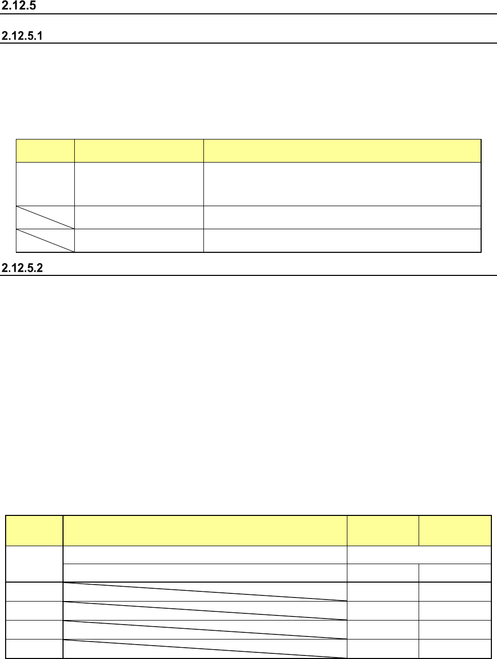
(2) Conditions for returning/discarding a component after checking the laser height
After checking the laser height, the system returns some components to their original positions
and discards other ones depending on their packaging styles as shown in Table below. The
system discards a component at a position set according to the setting of the menu item
"Compo Reject to" on the Component data screen. When “IC Collection Belt” or “Protect” is
set for the menu item “Compo Reject to,” the system discards a component according to this
setting.
For a component whose size is 1 mm or less, it may be placed on its side or be turned upside
down when it is returned to the original position. Therefore, the system displays the “Question”
screen to ask you how to handle it.
Note that you cannot pick up a component manually.
Packaging
style
Condition
Returning a
component
Discarding a
component
Tape The shorter side length of the external dimensions is 1 mm or less. Question screen *1
The shorter side length of the external dimensions is 1 mm or more. ○ ○ *2
Holder
○ ○ *2
Stick
― ○
MTC
○
○ *2
MTS
○
○ *2
*1 The system displays the screen to ask you whether to return a component or discard it. When the system
measures the laser height of components continuously, it displays this “Question” screen before starting
measurement.
*2 The system discards a component when you select “IC Collection Belt” or “Protect” for the menu item
“Comp reject to.”
(3) Selecting a feeder used to pick up a component
If two or more feeders are assigned to the same type of components in the Pick data, the
Part 1 Basic Operation Chapter 2 Production
2-124
system starts picking up components from one whose data was entered first of all.
(4) Changing the coordinates of a component pick-up position
If the system cannot pick up a component normally, change the coordinates of a component
pick-up position by entering them manually or teaching them.
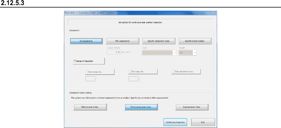
Continuous laser position inspection
(1) Component
Select one of the following buttons if you want to inspect only components that satisfy the
certain requirement(s).
1) All components
When you check this radio button, the system checks all components whose data is
specified in Component data.
2) Thin components
The system inspects only components whose height is lower than or equal to the value
set in the edit box.
3) Specific component types
The system inspects only components whose type is selected in the combo box.
4) Specific nozzle Number
The system inspects only components that use the nozzle selected in the combo box.
(2) Range of inspection
Check this check box if you want to check the components whose numbers are specified here
among components that satisfy the requirement(s) specified in the “Components” column.
When you check this check box, you can specify the following items.
1) Start comp. No.
Check this check box if you want to specify the component number of the first
component to be checked. After checking this check box, change the first component
number displayed in the edit box.
2) End comp. No.
Check this check box if you want to specify the component number of the last
component to be checked. After checking this check box, change the last component
number displayed in the edit box.
3) Only placement comp.
Check this check box if you want to check only components whose data is stored in
Placement data also.
(3) Component return setting
The screen that allows you to select how an inspected component is to be handled appears.
1) Returns every time