RS-1_instruction manual.pdf - 第479页
Part 1 B asic O peration Chapter 4 Cr eating a Produc tion Progra m 4- 144 When a holder is selected as a component supp ly unit, an ima ge of a tr ay is displayed a s show n b elow. When you touc h the displayed imag e …
Part 1 Basic Operation Chapter 4 Creating a Production Program
4-143
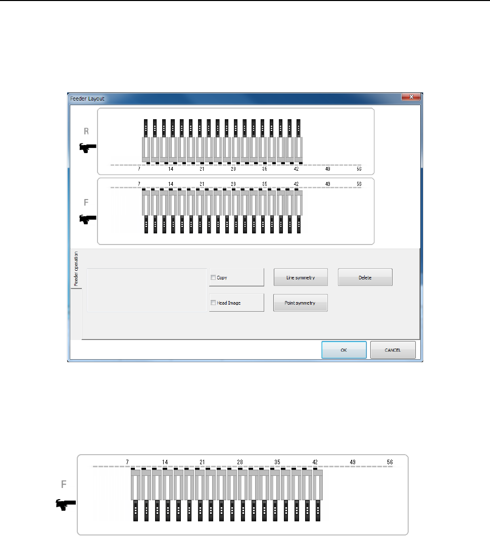
4.4.2.3 Feeder layout
The [Feeder Layout] command displays the feeder layout specified on the “Pick” data screen
graphically, and it allows you to check feeders with your eyes and/or handle the feeder layout.
(1) “Feeder layout” screen
When you select the [View]-[Feeder layout] commands from the menu, the following “Feeder
Layout” screen appears on the screen.
1) Bank image
On the “Feeder Layout” screen, the feeder layout specified on the “List” screen of the “Pick”
data is shown graphically.
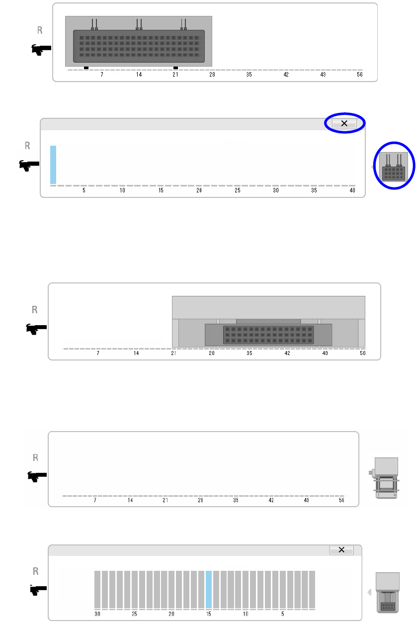
For the electric bank (RF) or the electric bank (RF/EF), the image shown below is
displayed.
Part 1 Basic Operation Chapter 4 Creating a Production Program
4-144
When a holder is selected as a component supply unit, an image of a tray is displayed as
shown below.
When you touch the displayed image of a tray, its enlarged image is displayed on the
screen.
To return to the original image display, touch the [×] button or the tray image displayed on
the right side of the screen.
See “(3) Copying/moving/deleting a feeder” of "4.4.2.3 Feeder layout" for how to operate it.
When a TR8SR is selected as a component supply device, the feeder layout is displayed
with the image of the TR8SR as shown below.
When you touch the displayed TR8SR image, the enlarged TR8SR image is displayed on
the screen.
When a MTC is selected as a component supply device, the feeder layout is displayed with
the image of the MTC as shown below.
When you touch the displayed MTC image, the enlarged MTC image is displayed on the
screen.
To return to the original TR8SR image screen, touch “×” or the MTC/MTS image displayed
on the right side of the screen.
Part 1 Basic Operation Chapter 4 Creating a Production Program
4-145
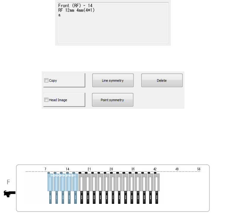
2) Component pick-up information
Information on the selected feeder is displayed here. As information on a feeder, the
component pick-up position, the supply unit and the component name are displayed.
For the feeder or the tray holder, the bank type is displayed at the pick-up position.
3) Operation buttons
The buttons used on the “Feeder Layout” screen are shown below.
(2) Display of an image of heads
If you check the <Head Image> button of the operation buttons, the head image appears on
the screen when you touch the “Feeder Layout” screen. Feeders from which the system
may be able to pick up components at the same time are displayed in light blue.
(3) Copying/moving/deleting a feeder
You can change the feeder layout by copying/moving/deleting a feeder on the bank image
screen.
1) Selecting a feeder
To copy/move/delete a feeder on the bank image screen, select the desired feeder. You
can select a feeder from only one bank. You cannot select any feeder from two or more
banks. The selected feeder is displayed in orange.