RS-1_instruction manual.pdf - 第715页
Part 2 Det ailed Desc ript ion of Eac h Fu nctio n Chapter 8 M achine Setup 8-7 2. Install the ZM STO P PER ① with t he screw ③ and press it agai nst the Z axis pulley and f asten w ith the screw ③ . 【 UNTI L H EAD Rev .…
Part 2 Detailed Description of Each Function Chapter 8 Machine Setup
8-6
6
Offset Placement After
Solder Screen-Printing
This function is just deleted, and placement is executed.
(2) How to set
1) Specify a device to be used by check button.
When a check mark is attached, this means a “Use” setting. If no check mark is
attached, this means a “No use” setting.
2) To change the no use status of the head to the usable status, release the head lock.
After releasing the head lock, make a return-to-origin for each head. When all the
heads are in the servo OFF status, make a return-to-origin for all the axes according to
instructions given in the screen.
3) To change the use status of the head to the no use status, fix the Z-axis of the head. In
this case, observe the instructions given in the screen.
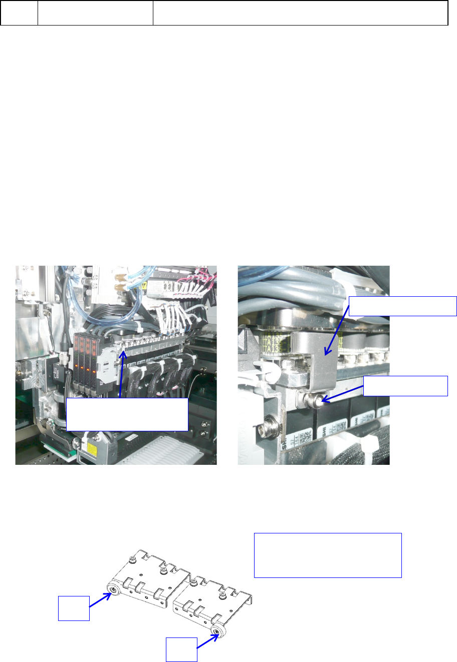
* To set the head and each axis (Z-axis) of the head to “No use”, fix the unused axes by the
following procedure.
【UNTIL HEAD Rev.A】
1. Install the ZM STOPPER ① at taps ③ on the side face of the head with set screws ②
and push it against the Z-axis pulley and then fix it with set screws ②.
2. When you change the setting of an unused axis so that it can be used, loosen the
screws ②, and remove the ZM STOPPER ① to release the fixed Z-axis.
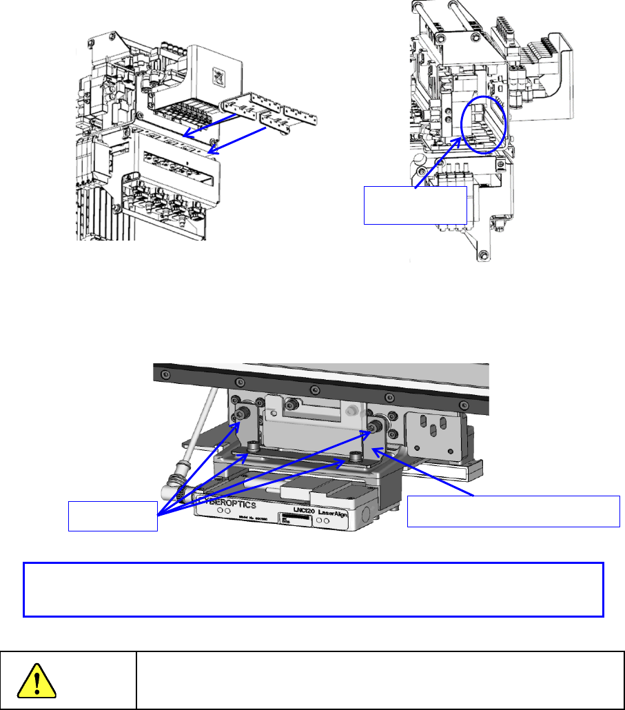
【AFTER HEAD Rev. A】
1. Attach cover cushion ② only to the place where the axis is fixed with ZM STOPPER ①.
① ZM STOPPER
② Set screw
③
Tap on the side
face of the head
For example.
When Z8 and Z1 are fixed
Z8
Z1
Part 2 Detailed Description of Each Function Chapter 8 Machine Setup
8-7
2. Install the ZM STOPPER ① with the screw ③ and press it against the Z axis pulley
and
f
asten with the screw ③.
【UNTIL HEAD Rev. A, Shared After.】
1. When not using the ZA axis, attach ZA_FIXED_BRACKET (40182877) and fix the ZA
axis.
Danger
To prevent an accident due to a sudden start, turn off the power
supply before starting operations.
- Make sure that the Z-axis is provided at the top position and install the fixture.
- Make sure that the Z-axis is fixed with the fixture.
ZA_FIXED_BRACKET (40182877)
Screw M3
Set screw③
Part 2 Detailed Description of Each Function Chapter 8 Machine Setup
8-8
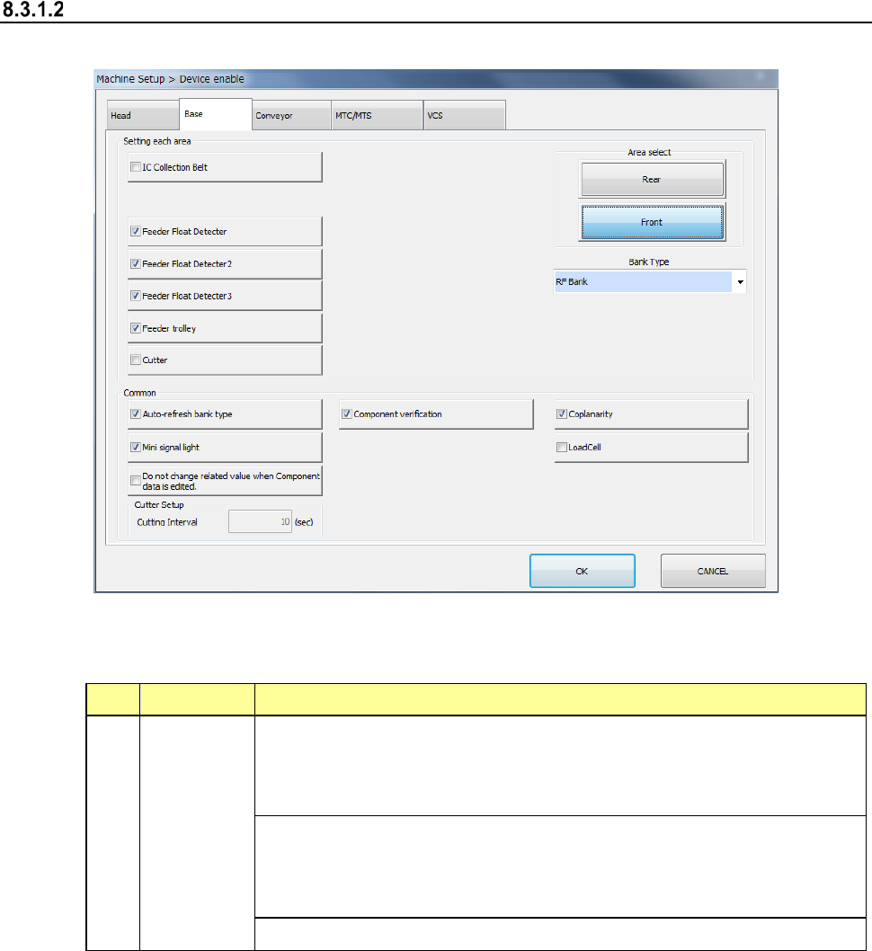
Base
When you select “Base”, the following screen appears.
When you click each tab, you can specify each of “Head,” “Base,” “Conveyor,” “MTS” and “VCS.”
(1) Setting items
No. Item Description
1 Base
Specify whether to use a device or not.
If you set one device not to be used on this tab, when it malfunctions the
system can continue picking up and placing components without
changing data of a production program.
Displays the bank type of each bank.
Note that when the machine is designed to be equipped with fixed banks
only, the front bank is fixed to the RF bank only, while the rear bank is
fixed to the RF/EF bank only.
Specify the repetition interval of cutter setting.
If a production program requires any function displayed on the screen above to finish placing
a component on a board completely, whether the system can place a component actually is
shown in Table.