RS-1_instruction manual.pdf - 第280页
Part 1 B asic O peration Chapter 2 Pr oduction 2- 169 (3) C reate a fee der layout for non - st op operat i on with th e Optimization funct ion. Specify the opt imization require m ents, and then perform the opt imizatio…
Part 1 Basic Operation Chapter 2 Production
2-168
2.17 Non-stop Operation (Option)
This is a mechanism for improving the operation rate of the machine by continuing PWB production
without stopping the machine when components run out.
To perform the Non-stop operation, prepare the same set of feeders both on the front feeder bank
and on the rear feeder bank.
This allows the machine to pick up a component from the feeder installed on the rear feeder bank
even though components run out at the feeder installed on the front feeder bank, and then to
continue to produce a PWB without stopping.
You can remove the cause of the error of the feeder installed on the front feeder bank at which
components run out while the machine is producing a PWB by picking up components from the
feeder on the rear feeder bank, and then allow the machine to pick up components from the feeder
on the front feeder bank again also.
In addition, if you prepare the set of feeders for the next PWB production, you can shorten the time
required for changeover of feeders.
When you install an MTS (TR-5S or TR-5D) on the machine, any feeder cannot be installed on
the rear side. Therefore, you cannot execute the non-stop operation function by using a
feeder to supply the machine with components.
Procedure for creating data
(1) Create data.
Follow the normal data creation procedure to create a production program for feeders installed
on the front side.
(2) Create a non-operation feeder layout with the [Feeder Layout] command.
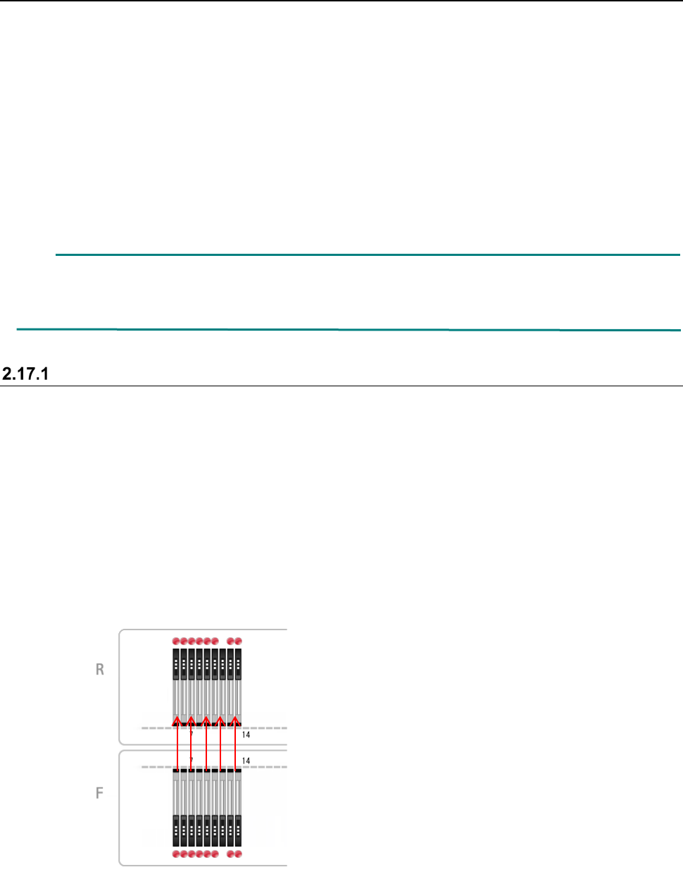
Use the “Line symmetry” copy or the “Point symmetry” copy of the Feeder Layout function to
assign Pick data to the rear bank.
- Line symmetry copy
When you assign Pick data with selecting the “Line symmetry,” priority is given to the “cycle
time.”
Each feeder is copied to the opposite side so that the hole number of a feeder on the front
side will face the hole number of a feeder on the rear side, and the coordinates of a
component pick position on both sides become the same ones.
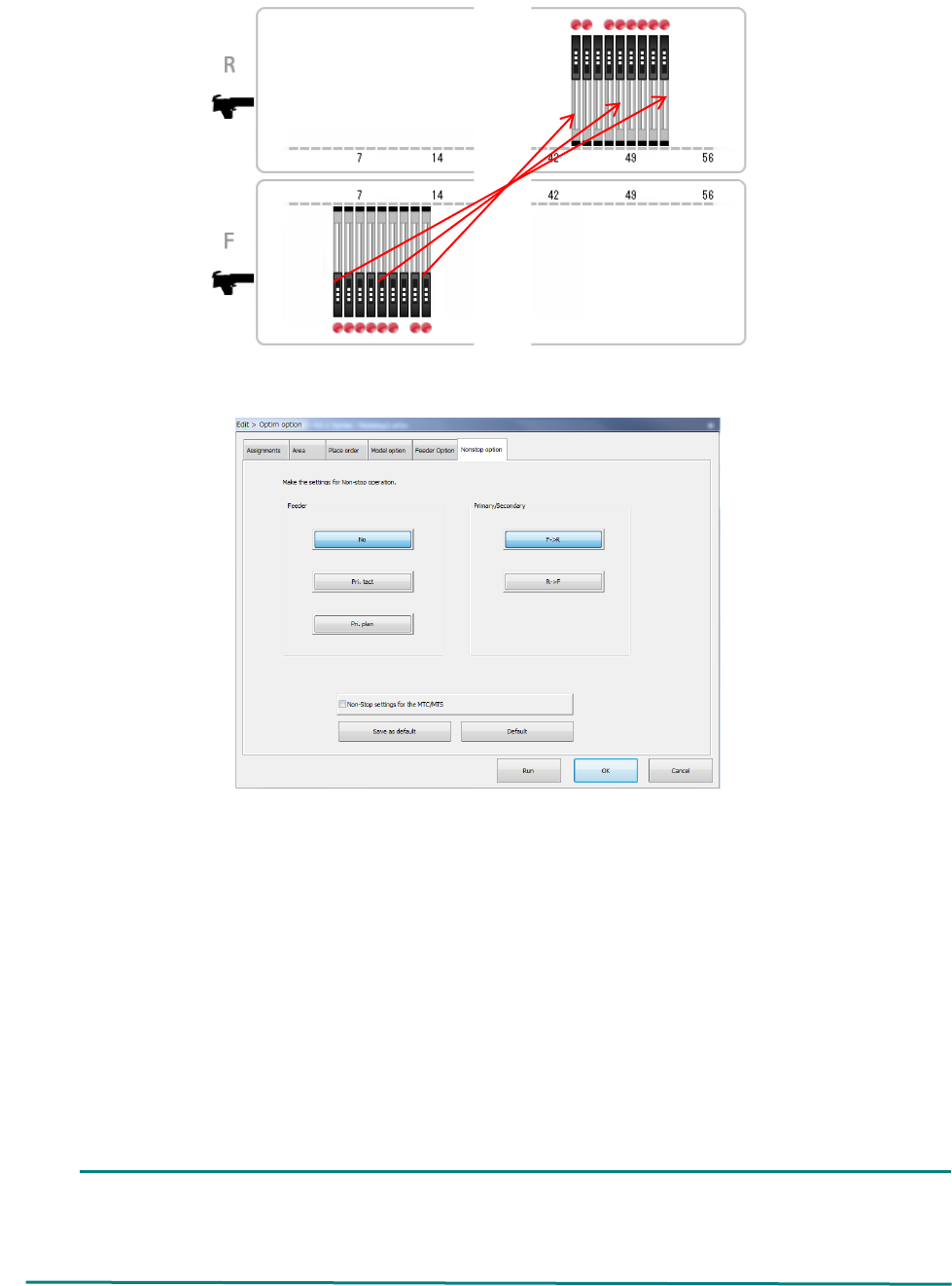
- Point symmetry
When you assign Pick data with selecting the “Point symmetry,” priority is given to the
“planning” (setup)
Each feeder is copied to the hole position symmetrical with respect that of a feeder on the
opposite side, and the feeder layouts of the rear and the front become the same as each
other when the feeder banks are viewed from the front.
Part 1 Basic Operation Chapter 2 Production
2-169
(3) Create a feeder layout for non-stop operation with the Optimization function.
Specify the optimization requirements, and then perform the optimization function.
Feeder: Specify how to assign feeders during Non-stop operation.
- No : The system does not perform Non-stop operation.
- Pri. tact : The system creates the feeder layout by giving priority to the cycle time (line
symmetry).
- Pri. plan : The system creates the feeder layout by giving priority to the planning (setup)
(point symmetry).
Primary/Secondary: Specify which side is to be used mainly during Non-stop operation, the
front or the rear.
Select the <F ->R> button when the reference side is set to the front or
the <R -> F> button when it is set to the rear side.
Non-Stop settings for the MTC/MTS: Specify whether an MTC/MTS is to be used for Non-stop
operation or not.
When the RF/EF bank is specified for the front side, an EF type feeder is used on this side,
and the RF bank is specified for the rear side, any EF type feeder cannot be assigned to the
RF bank. Therefore, the system cannot perform PWB production in optimized order.
In such a case, produce a PWB in input order.
Part 1 Basic Operation Chapter 2 Production
2-170
Changing the machine operation mode
The Non-stop operation function allows you to switch the operation mode between two modes,
Non-stop operation mode and Normal operation mode (referred as to “JUKI standard mode”
hereinafter).
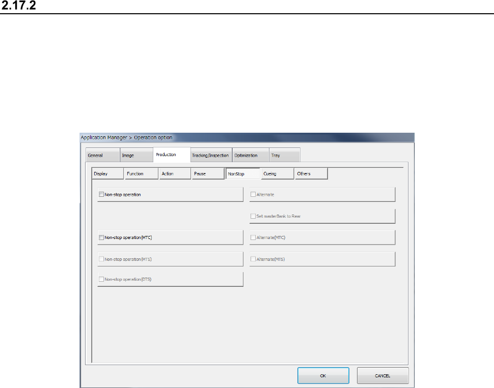
To switch the operation mode, display the “NonStop” tab of the “Production” tab invoked from the
“Operation option” screen.
When you check off the “Non-stop operation” check box on the “NonStop” tab of the “Production”
tab, the system is put in “Non-stop operation mode.” When you uncheck this check box, the
system is put in “JUKI standard mode.”
In Non-stop operation mode, priority is given to pick-up of components from the master feeder bank.
Even while a component is being picked up from the slave feeder bank, the next component is
picked up from the master feeder bank when the master feeder bank is refilled with components and
you set the bank switch to ON.
When you check off the “Alternate” check box, the system is put in “Alternate production mode.” In
Alternate production mode, the banks are switched alternately if components run out on one of
these banks during PWB production in Non-stop operation mode (that is, even though the master
feeder bank is refilled with components, components continue to be picked up from the slave bank
until components run out on the slave bank).
When you check off the “Non-stop operation” check box, the following items are set to the “unused”
state without precondition, and you cannot select any of them.
1. When components run out, production pauses.
2. Stop system on any error.
3. Measure component height when restarting after component run out.
4. Perform component verification when restarting after component run out.
Components are picked up from mainly the master feeder bank during PWB production. The
master feeder bank can be switched to another one, and the rear feeder bank can be used as the
master feeder bank also.
To use the rear feeder bank as the master feeder bank, check off the “Set masterBank to Rear”
check box. When the “Set masterBank to Rear” check box is unchecked, the front feeder bank is
used as the master feeder bank.