RS-1_instruction manual.pdf - 第211页
Part 1 B asic O peration Chapter 2 Pr oduction 2- 100 When you touc h the displayed MTC image, the enl arged MTC image is disp layed. T o return to the origina l bank image scr een, t ouch “×” or the MTC image d i splay …
Part 1 Basic Operation Chapter 2 Production
2-99
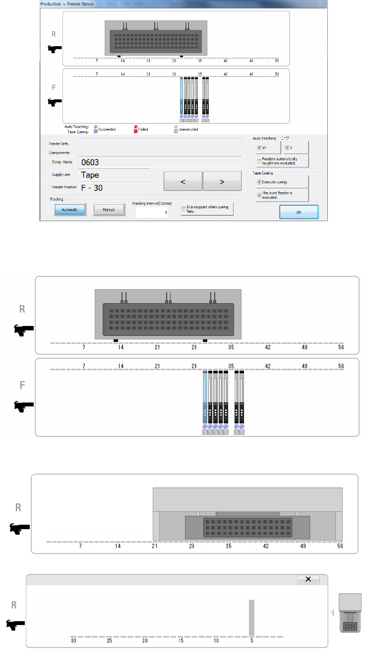
(1) Feeder layout
The system displays the layout of the feeder that is to be used with a production program you
select on the top of the screen.
When a TR8SR is used as a component supply device, the feeder layout is displayed with the
image of a TR8SR as shown below.
When you touch the displayed TR8SR image, the enlarged TR8SR image is displayed.
To return to the original TR8SR image screen, touch “×” or the TR8SR image displayed on
the right side of the screen.
When a component supply device is a TR6S/6D, an image of an MTS is shown on the right
side of the image of the bank.
Part 1 Basic Operation Chapter 2 Production
2-100
When you touch the displayed MTC image, the enlarged MTC image is displayed.
To return to the original bank image screen, touch “×” or the MTC image displayed on the right
side of the screen.
(2) Components (detailed information on the target component)
Information on the feeder of the selected bank is displayed here.
Menu item
Description
Comp. Name
Displays the name of a target component in large characters.
Supply Unit
Displays the type of a target component in large characters.
Feeder Position
Displays the supply position of a target component in large characters.
When you press the < < > button or < > > button, another target component is selected, and
the detailed information is updated.
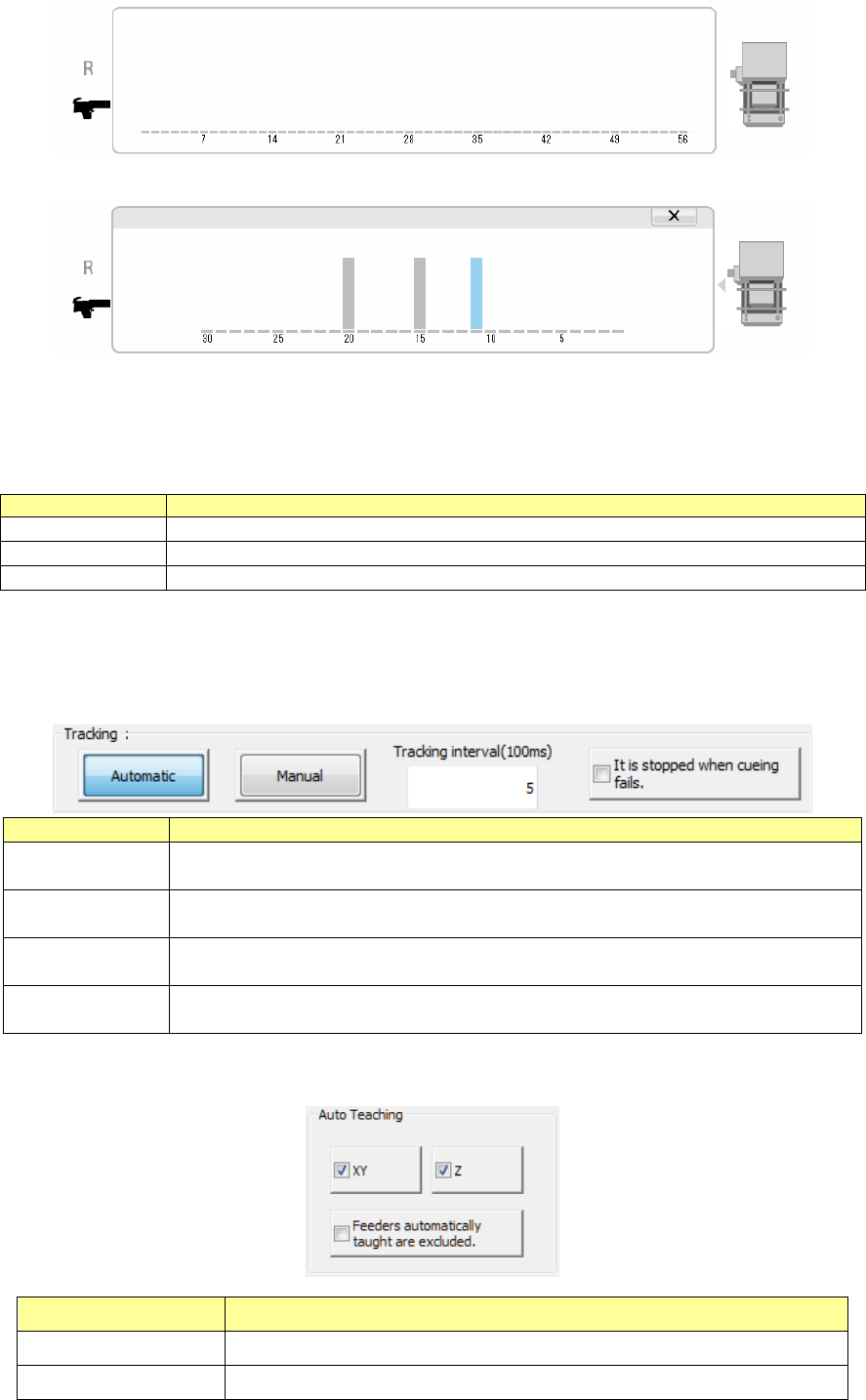
(3) Tracking
Select how to move to a component pick-up position to be tracked.
Tracking
Description
Automatic
Automatically tracks the next pick-up position after tracking the component pick-up
position and then pauses.
Manual
The system tracks a component pick-up position, and then pauses.
The system tracks the next pick-up position in response to the operator’s input.
Tracking
Set the time period the system pauses at each component pick-up position if it tracks
pick-up points automatically.
It is stopped when
cueing fails.
Stops automatic feeding if cueing fails to cue (head) a component.
(4) Auto Teaching
Set the auto teaching operation to track a component pick-up position.
Auto Teaching Description
XY Automatically teaches the XY.
Z Automatically teaches the Z.
Part 1 Basic Operation Chapter 2 Production
2-101
Feeders automatically
taught are excluded.
Prohibits feeders that were automatically taught successfully once from being
taught again automatically.
(5) Tape cueing
Set component cueing (heading) to track a component pick-up position.
Tape cueing Description
Execute cueing Cues a component.
The cued feeder is
excluded.
Prohibits a component from being cued at a feeder whose component has
been cued already.
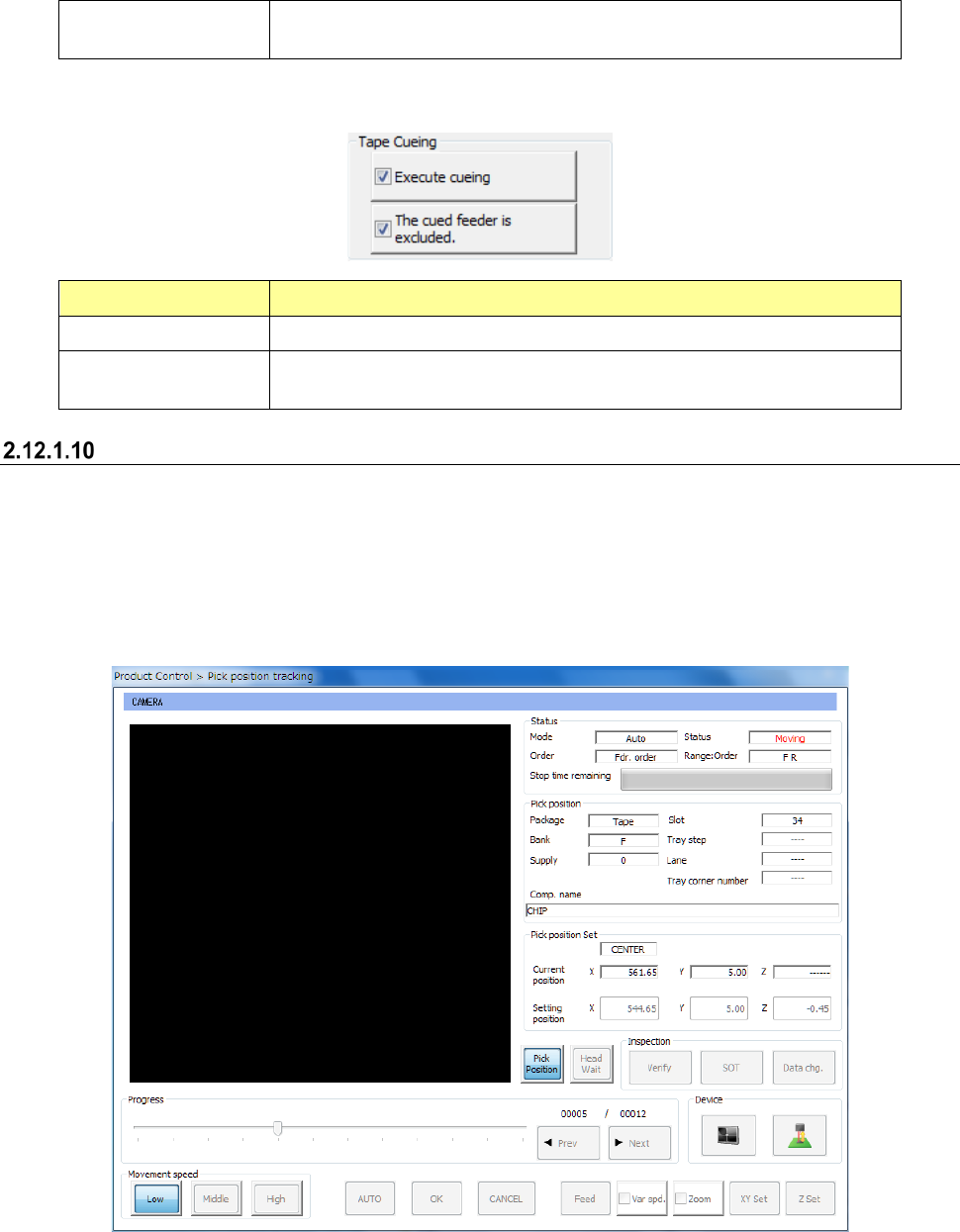
Pick Trace
This button starts up the screen for tracking a component pick-up position.
Only feeders specified with the menu item “Tracking order” on the “Pick position tracking” screen
are to be traced.
See Section 4.5.6.4 “Place” and Section 4.5.6.5 “Pick position/Pick height” of Chapter 4 “Creating a
Production Program” for details.
- Pick Trace