RS-1_instruction manual.pdf - 第565页
Part 1 B asic O peration Chapter 4 Cr eating a Produc tion Progra m 4- 230 1) Comp. height This functi on measures t he height of a compo nent with laser . At the same time, the syst em automati cally calculates t he opt…
Part 1 Basic Operation Chapter 4 Creating a Production Program
4-229
4.5.7 Measurement/Inspection
No.
Submenu
Overview
1
Current component
Measures each detailed value of the Component data
2
All component
Measures each detailed value of two or more Component data records.
3
PWB Height
Measures the height of the surface of a PWB at a component placement position.
4 Recognize
Recognizes a component with a VCS to check to see if the component can be
centered.
5 Verify speed
Performs quasi-production operation to check errors of the moving XYθ-axes
during operation.
6 Vision teaching
Measures a ball of a ball component (general-purpose vision component, BGA
and FBGA).
7 Bad mark teaching
Use the OCC unit to teach a mark in order to determine whether to produce a
circuit.
To avoid a risk of injury, do not put your hands inside the machine or move
your face or head close the machine while the system is teaching data.
4.5.7.1 Current component/All component (Single measurement/Continuous measurement)
These functions cause the system to pick up an actual component to measure it with laser or a
VCS, and then reflect the measured data into a production program.
(1) Measurement mode
Two types of modes are provided for measurement operation: “Continuous Measurement” and
“Single Measurement.” Select the desired mode from the menu.
The command and its corresponding measurement mode are shown in Table below:
Measurement mode Description
Single Measurement Measures a component displayed on the Component "Form" screen.
Continuous Measurement Measures all components/components which satisfy the conditions specified in a
production program. In Single Measurement mode, you can measure a
component which failed to be measured for some reason individually.
(2) Measurement items
The items to be measured are outlined in the table below.
Measure item What to measure Remarks
Comp. height
Component height -
Calculation of the optimal laser centering value
Components to be
centered with laser
only
Laser height
Threshold value for a chip tombstone error
Outline
Outer dimensions of a component (length and width) -
Calculation of the optimal nozzle number -
Vacuum level Vacuum level to be applied when an actual component is picked up -
Lead Information
Dimensions of a lead of a component
Components to be
centered with a VCS
only
Lead pitch
Lead length
Number of leads/information on a missing lead(s)
CAUTION
Part 1 Basic Operation Chapter 4 Creating a Production Program
4-230
1) Comp. height
This function measures the height of a component with laser.
At the same time, the system automatically calculates the optimum laser height and the value to
be used for judging if a chip is placed on its side (if a tombstone error occurs).
The measuring methods are shown below.
Target component
Method
Laser recognition component
Vision recognition component
① The component is moved up and down.
②
The shadow range of the component is specified as the height.
2) Outline
The length and the width of a component are measured with laser or a vision recognition unit.
The optimal nozzle number is automatically calculated also. The measuring methods are shown
below.
Target component
Method
Laser recognition component ① The current component angle is obtained by laser.
② By rotating the component at a 0-degree angle in the theta direction, the
obtained laser width is specified as the crosswise dimension.
③ By rotating the component at a 90-degree angle in the theta direction, the
obtained laser width is specified as the lengthwise dimension.
Vision recognition component
① The component is recognized with a vision recognition unit to obtain its outer
dimensions.
② The values obtained from a response is specified as crosswise and
lengthwise dimensions.
3) Vacuum level
This function measures the vacuum pressure used to pick up a component. The measuring
methods are shown below.
Target component Method
Laser recognition component
Vision recognition component
1. The component is picked up to obtain the vacuum pressure of the head
2. The obtained value is specified as the vacuum pressure for picking up a
component.
4) Lead Information
The lead information is measured by a vision recognition unit. This measurement can be
executed only for vision centering components to be centered with a VCS.
The measuring method is shown below.
Target component
Method
Vision recognition component
1. A component is recognized with a vision recognition unit to obtain the lead
information.
2. The obtained values are specified as the lead dimensions.
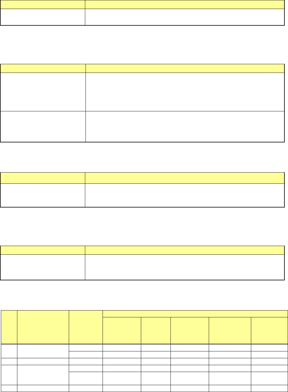
(3) Measurement restrictions to be imposed depending on the component type
Items the system can measure are restricted according to the component type of the Component
data to be measured as shown in the table below.
No Component type
Centering
method
Measurement items
Component
height
Laser
height
Dimensions
of a
component
Vacuum
pressure for
picking up a
component
Lead
information
1
Square chip
Laser
○
○
○
○
Vision
○
○
2
MELF
Laser
○
○
○
○
3
Aluminum
electrolytic
capacitor
Laser
○
○
○
Vision
○ ○
4
GaAsFET
Laser
○
○
○

Part 1 Basic Operation Chapter 4 Creating a Production Program
4-231
No Component type
Centering
method
Measurement items
Component
height
Laser
height
Dimensions
of a
component
Vacuum
pressure for
picking up a
component
Lead
information
Vision
○
○
5
SOT
Laser
○
○
○
○
6 SOP
Laser
○
○
△
○
Vision
○
○
*1
○
○
*1
7 SOJ
Laser
○
○
○
Vision
○
○
8 QFP
Laser
○
○
△
○
Vision
○
○
*1
○
○
*1
9 PLCC(QFJ)
Laser
○
○
○
Vision
○
○
10 PQFP(BQFP)
Laser
○
○
△
○
Vision
○
○
*1
○
○
*1
11 TSOP
Laser
○
○
△
○
Vision
○
○
*1
○
○
*1
12 TSOP2
Laser
○
○
△
○
Vision
○
○
*1
○
○
*1
13 BGA
Laser
○
○
○
Vision
○
○
14
Network resistor
Laser
○
○
○
15
Trimmer
Laser
○
○
○
16
Unidirectional
lead connector
Laser
○
○
○
○
*2
Vision
○
○
○
*1, *2
17 J-lead connector
Laser
○
○
○
Vision
○ ○
18 Gull-wing socket
Laser
○
○
○
Vision
○
○
19
Key socket with
bumper
Laser
○
○
○
Vision
○
○
20
Other
components
Laser ○ ○ ○
21
Bidirectional lead
connector
Laser
○
○
△
○
○
*2
Vision
○
○
*1
○
○
*1, *2
22
SOP with heat
sink
Laser
○
○
△
○
Vision
○
○
*1
○
23
FBGA
Vision
○
○
24 Z-lead connector
Laser
○
○
○
Vision
○
○
25
Extended lead
connector
Vision ○ ○
26
General-purpose
vision component
Vision ○ ○
27
Square chip
(LED)
Laser ○ ○ ○ ○
28
QFN
Laser
○
○
○
29
Outline
recognition
component
Vision ○ ○
〇: Measurable
△: The measurement result obtained by setting the centering method to "Vision" can be used.
*1 Only components having 7 leads or more per column. (SOP 14-pin can be measured.)
*2 Components composed of the same lead shape and provided with no arm or metal in the lead
both-end section.
The lead information may not be measured depending on the lead conditions of the component to
be measured.
The measurement function is to be executed for components whose outer dimension is 33.5 mm
or less.