RS-1_instruction manual.pdf - 第63页
Part 1 B asic O peration Chapter 1 Overv iew of the Machine 1- 45 2) Bottom side of a boar d Any sup port pin c ann ot set in thi s are a range. Standard s pecificati on: 50 to 370mm Extra - large specif ication: 50 to 5…
Part 1 Basic Operation Chapter 1 Overview of the Machine
1-44
50 to 950 mm
Standard specification: 50 to 370 mm
Extra
-
large specification:
50 to 560 mm
Component not placeable area
Printed circuit board specifications
(1) Board requirements
Minimum
size
(L x W)
Maximum size (L x W)
Thickness
T
Maximum
allowable
mass
Allowable warpage
1-buffer 3-buffer
Standard
board size
50 x 50 mm
650 x 370 mm
(One clamp)
950 x 370 mm
(Twice clamp)
360 x
370 mm
0.3~4.0 mm 3,000 g
0.2 mm or less per 50 mm in
the up/down direction, and 1
mm or less
upwards/downwards
(Conforming to the JIS B
8461.)
Extra-large
board size
650 x 560 mm
Note: “L” stands for the dimension in the board transporting direction, while “W” stands for the
dimension in the direction at right angles to “L,” and “W/L” shall be equal to 2 or less.
Note: A low reflectance PWB may not be detected by a conveyor sensor, independent of materials and
colors of the PWB.
(2) Board limitations
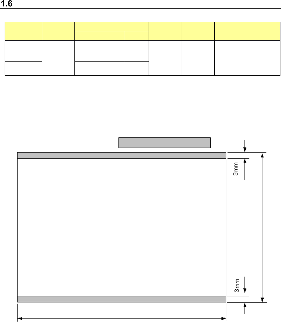
1) Topside of a board
Conveyor rail fixed side
Part 1 Basic Operation Chapter 1 Overview of the Machine
1-45
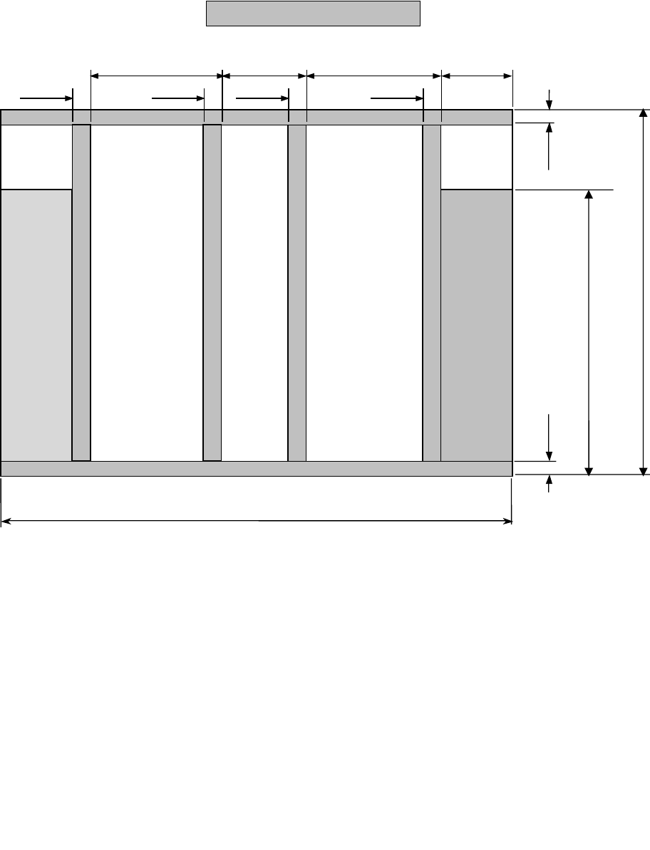
2) Bottom side of a board
Any support pin cannot set in this area range.
Standard specification:
50 to 370mm
Extra
-
large specification:
50 to 560mm
3mm
3mm
57.5mm
8mm
8mm
220mm
87mm
8mm
8mm
220mm
Left → Right
flow
Stopper movable range 0 to 320mm
Left ← Right
flow
Conveyor rail fixed side 50 to 650 mm
Part 1 Basic Operation Chapter 1 Overview of the Machine
1-46
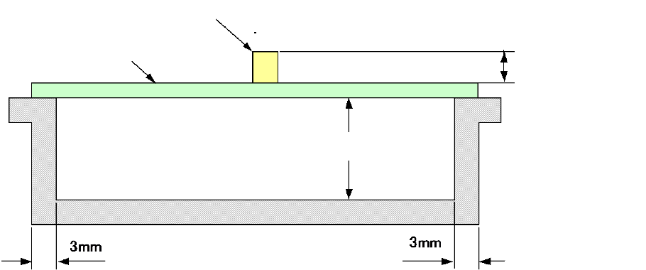
3) Height range of components to be placed on boards and that of the board rear side when
transported
*1: Change with software 1/3/6/12/20/25 mm according to the component height
*2: The height of an existing component that has been mounted should be within the
component height specification.
*3: For the component height of the laser recognition component, see "1-5 Applicable
components, (2) Recognition height of laser recognition component; for the component
height of the image recognition component, see "1-5 Applicable components, (3)
Recognition height of image recognition component".
PWBs clamping method
This is a method to use the PWB top surface as a reference to have both the PWB front and rear
ends each at the fixed and movable sides supported to the transport rails, then, to clamp the
PWBs.
PWB width adjusting methods
Standard: Automatic PWB width adjusting method via a motor
Board
Component
Area of the rear side of a board in
which a component can be placed
Maximum 40 mm
*1